


L
i
n
M
o
t
Motion Control SW
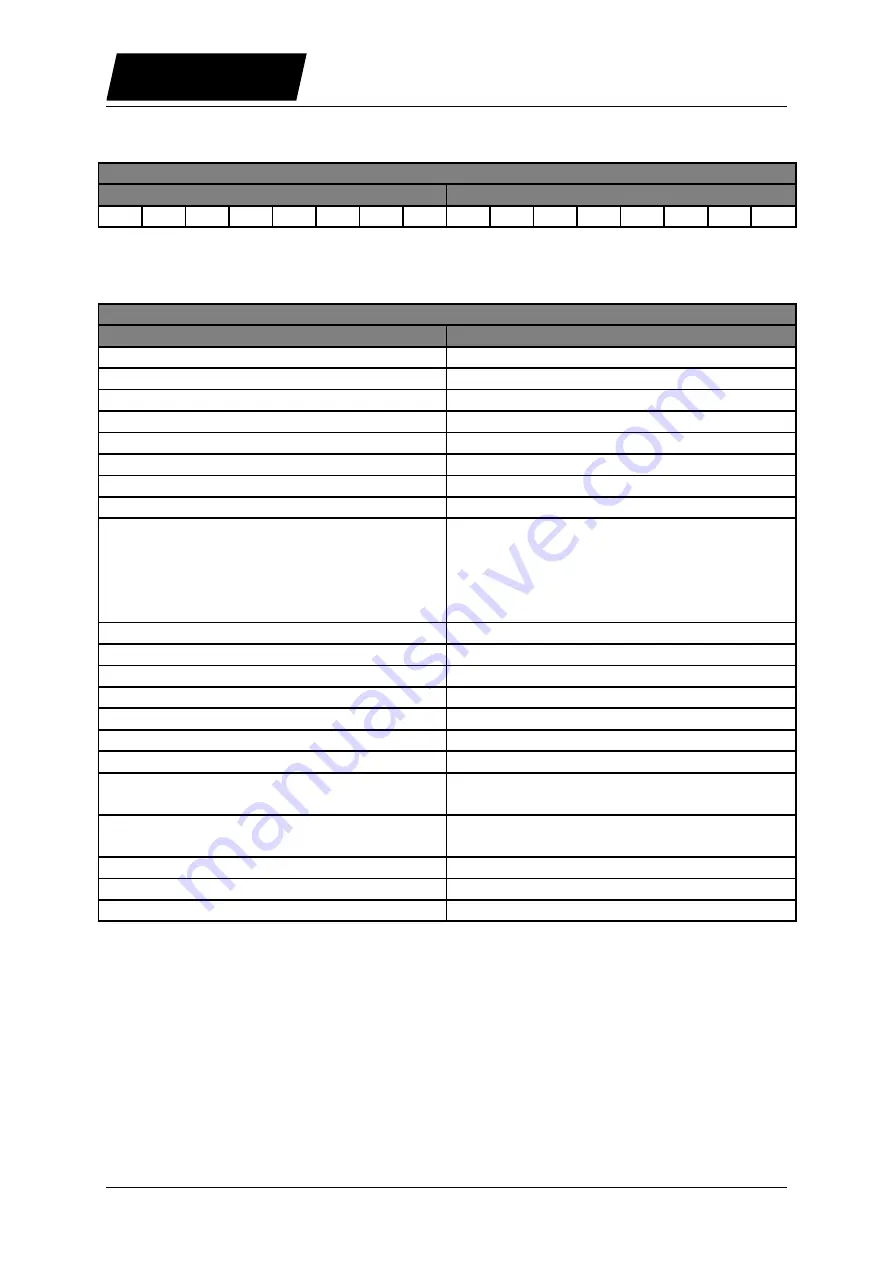
The state machine can be followed in the PLCs with fieldbus using the the StateVar. This
response word can be configured for any supported fieldbus.
State Var
Main State
Sub State
15
14
13
12
11
10
9
8
7
6
5
4
3
2
1
0
The State Var is divided into two sections: the Main State section (high byte) contains directly
the number of the state machine, the content of the Sub State (low byte) is state depending.
State Var
Main State
Sub State
00: Not Ready To Switch On
0
01: Switch On Disabled
0
02: Ready To Switch On
0
03: Setup Error
Error Code which will be logged
04: Error
Logged Error Code
05: HW Tests
0 (Not yet defined)
06: Ready To Operate
0 (Not yet defined)
07: -
08: Operation Enabled
Bits 0..3: Motion Command Count
Bit 4: Event Handler Active
Bit 5: Motion Active
Bit 6: In Target Position
Bit 7: Homed
09: Homing
0Fh: Homing Finished
10: Clearance Check
0Fh: Clearance Check Finished
11: Going To Initial Position
0Fh: Going To Initial Position Finished
12: Aborting
Not yet defined
13: Freezing
Not yet defined
14: Quick Stop (Error Behaviour)
Not yet defined
15: Going To Position
0Fh: Going To Position Finished
16: J
01h: Moving positive
0Fh: JFinished
17: Jogging -
01h: Moving negative
0Fh: Jogging -Finished
18: Linearizing
Not yet defined
19: Phase Search
Not yet defined
20: Special Mode
Not yet defined
Page 12/91
User Manual Motion Control SW / 06/12/2013
NTI AG / LinMot