Repair information
Removal precautions
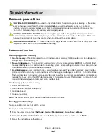
CAUTION—SHOCK HAZARD:
To avoid the risk of electrical shock and to prevent damage to the printer,
remove the power cord from the electrical outlet before you connect or disconnect any cable or
electronic card or assembly for personal safety and to prevent damage to the printer. Disconnect any
connections between the printer and computers or peripherals.
CAUTION—POTENTIAL INJURY:
The printer weight is greater than 18 kg (40 lb) and requires two or
more trained personnel to lift it safely. Always use the hand holds on the sides of the printer. Make sure
that your fingers are not under the printer when you lift or set the printer down.
CAUTION—HOT SURFACE:
The inside of the printer might be hot. To reduce the risk of injury from a hot
component, allow the surface to cool before touching.
Data security notice
Identifying printer memory
•
Volatile memory
—The printer uses standard random access memory (RAM) to buffer user data temporarily
during simple print and copy jobs.
•
Non-volatile memory
—The printer may use two forms of non-volatile memory: EEPROM and NAND (flash
memory). Both types are used to store the operating system, printer settings, network information, scanner
and bookmark settings, and embedded solutions.
•
Hard disk memory
—Some printers have a hard disk drive installed. The printer hard disk is designed for
printer-specific functionality and cannot be used for the long
‑
term storage of data that is not print-related.
The hard disk does not provide the capability for users to extract information, create folders, create disk or
network file shares, or transfer FTP information directly from a client device. The hard disk can retain buffered
user data from complex print jobs, form data, and font data.
The following parts can store memory:
•
Printer control panel
•
User interface controller card (UICC)
•
Controller board
•
Optional hard disks
Note:
The printer control panel and controller board contain NVRAM.
Erasing printer memory
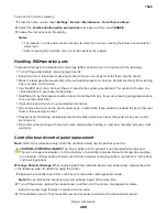
To erase volatile memory, turn off the printer.
To erase non-volatile memory:
1
From the home screen, touch
Settings
>
Device
>
Maintenance
>
Out of Service Erase
.
2
Select the
Sanitize all information on nonvolatile memory
check box, and then touch
ERASE
.
3
Follow the instructions on the display.
7528
Repair information
295
Summary of Contents for XC4150
Page 34: ...7528 34 ...
Page 276: ...7528 276 ...
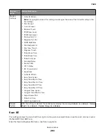
Page 294: ...Scan SE Scanner Info 7528 Service menus 294 ...
Page 317: ...3 Remove the screw B from the lower left side of the cover B 7528 Repair information 317 ...
Page 320: ...3 Remove the three screws A 7528 Repair information 320 ...
Page 327: ...3 Remove the E clip B 4 Remove the E clip C 7528 Repair information 327 ...
Page 358: ...5 Remove the two screws D from under the gear box 7528 Repair information 358 ...
Page 360: ...3 Disconnect the cable A from the LVPS 7528 Repair information 360 ...
Page 370: ...3 Disconnect the motor cable A A 7528 Repair information 370 ...
Page 371: ...4 Remove the four screws B and then remove the motor B 7528 Repair information 371 ...
Page 374: ...4 Disconnect the cable B 5 Remove the screw C securing the HVPS C 7528 Repair information 374 ...
Page 400: ...14 Remove the clip M and then remove the spacer 7528 Repair information 400 ...
Page 403: ...7528 Repair information 403 ...
Page 414: ...5 Remove the screw C from the printhead 7528 Repair information 414 ...
Page 429: ...8 Route the ADF cable through the flatbed 9 Remove the ADF 7528 Repair information 429 ...
Page 437: ...7 Disconnect the two cables B on the controller board 7528 Repair information 437 ...
Page 443: ...5 Remove the screw D and then remove the scanner tilt D 7528 Repair information 443 ...
Page 478: ...7528 478 ...
Page 485: ...7528 485 ...
Page 487: ...Assembly 1 Covers 1 2 4 6 7 8 9 1 14 10 3 5 13 13 11 11 12 7528 Parts catalog 487 ...
Page 489: ...Assembly 2 Covers 2 14 7528 Parts catalog 489 ...
Page 491: ...Assembly 3 Control panel 5 4 3 2 1 7528 Parts catalog 491 ...
Page 493: ...Assembly 4 ADF and flatbed 1 3 11 10 4 9 5 6 7 8 2 7528 Parts catalog 493 ...
Page 495: ...Assembly 5 Fuser 1 7528 Parts catalog 495 ...
Page 497: ...Assembly 6 Transfer module 1 2 7528 Parts catalog 497 ...
Page 499: ...Assembly 7 Paper feed 8 2 1 2 4 7 3 5 5 6 7528 Parts catalog 499 ...
Page 501: ...Assembly 8 Paper path 1 8 6 2 3 1 10 5 7 9 4 7528 Parts catalog 501 ...
Page 503: ...Assembly 9 Paper path 2 1 4 2 5 10 3 6 9 7 8 7528 Parts catalog 503 ...
Page 505: ...Assembly 10 Duplex 9 8 3 3 7 6 1 1 2 4 5 7528 Parts catalog 505 ...
Page 507: ...Assembly 11 Electrical 16 2 3 4 5 7 8 9 11 12 13 15 6 1 14 10 7528 Parts catalog 507 ...
Page 510: ...7528 Parts catalog 510 ...
Page 511: ...Assembly 12 550 sheet tray option 1 2 1 7528 Parts catalog 511 ...
Page 513: ...Assembly 13 550 sheet tray option 2 1 2 3 4 12 11 6 13 5 9 10 7 8 7528 Parts catalog 513 ...
Page 515: ...Assembly 14 Adjustable stand 2 2 3 3 1 7528 Parts catalog 515 ...
Page 518: ...7528 Parts catalog 518 ...
Page 520: ...7528 520 ...
Page 527: ...3 Apply the changes 7528 Appendix B Options and features 527 ...
Page 528: ...7528 528 ...
Page 554: ...7528 554 ...
Page 568: ...7528 Part number index 568 ...
Page 574: ...7528 Part name index 574 ...

