Using a network computer
Using the File Transfer Protocol (FTP)
Make sure that the printer is in ready state before flashing.
1
Turn on the printer.
2
Obtain the IP address:
•
From the home screen
•
From the TCP/IP section of the Network/Ports menu
3
From the command prompt of a network computer, open an FTP session to the printer IP address.
4
Use a PUT command to place the firmware file on the printer.
The printer performs a POR sequence and terminates the FTP session.
5
Repeat steps 2 through 4 for the other files.
Using the Embedded Web Server
Make sure that the printer is in ready state before flashing.
1
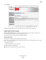
Open a Web browser, and then type the printer IP address.
2
From the home page, navigate to
Configuration
>
Update Firmware
.
3
Select the file to use.
The printer performs a POR sequence and terminates the FTP session.
4
Repeat steps 2 through 3 for the other files.
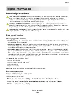
Backing up eSF solutions and settings
Note:
Export the eSF solutions and settings from the printer before replacing the controller board.
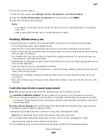
Exporting eSF solutions and settings file
1
Reset the printer into Invalid engine mode. See
“Entering Invalid engine mode” on page 291
2
Open a Web browser, and then type the printer IP address.
Note:
If the Web page cannot be accessed or an error occurs when starting the printer into Invalid engine
mode, then data backup is not an option. Inform the customer that the data cannot be saved.
3
Click
Apps
, click
Export Configuration
, and then select one of the options in the dropdown menu.
4
Click
Export
.
Note:
There is a size limit of 128 KB on the export file.
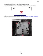
Disconnecting ribbon cables
Warning—Potential Damage:
The ribbon cable and its socket may get damaged if it is not properly
disconnected. When disconnecting the cable, hold its connector and press its tab before unplugging it.
7528
Repair information
302
Summary of Contents for XC4150
Page 34: ...7528 34 ...
Page 276: ...7528 276 ...
Page 294: ...Scan SE Scanner Info 7528 Service menus 294 ...
Page 317: ...3 Remove the screw B from the lower left side of the cover B 7528 Repair information 317 ...
Page 320: ...3 Remove the three screws A 7528 Repair information 320 ...
Page 327: ...3 Remove the E clip B 4 Remove the E clip C 7528 Repair information 327 ...
Page 358: ...5 Remove the two screws D from under the gear box 7528 Repair information 358 ...
Page 360: ...3 Disconnect the cable A from the LVPS 7528 Repair information 360 ...
Page 370: ...3 Disconnect the motor cable A A 7528 Repair information 370 ...
Page 371: ...4 Remove the four screws B and then remove the motor B 7528 Repair information 371 ...
Page 374: ...4 Disconnect the cable B 5 Remove the screw C securing the HVPS C 7528 Repair information 374 ...
Page 400: ...14 Remove the clip M and then remove the spacer 7528 Repair information 400 ...
Page 403: ...7528 Repair information 403 ...
Page 414: ...5 Remove the screw C from the printhead 7528 Repair information 414 ...
Page 429: ...8 Route the ADF cable through the flatbed 9 Remove the ADF 7528 Repair information 429 ...
Page 437: ...7 Disconnect the two cables B on the controller board 7528 Repair information 437 ...
Page 443: ...5 Remove the screw D and then remove the scanner tilt D 7528 Repair information 443 ...
Page 478: ...7528 478 ...
Page 485: ...7528 485 ...
Page 487: ...Assembly 1 Covers 1 2 4 6 7 8 9 1 14 10 3 5 13 13 11 11 12 7528 Parts catalog 487 ...
Page 489: ...Assembly 2 Covers 2 14 7528 Parts catalog 489 ...
Page 491: ...Assembly 3 Control panel 5 4 3 2 1 7528 Parts catalog 491 ...
Page 493: ...Assembly 4 ADF and flatbed 1 3 11 10 4 9 5 6 7 8 2 7528 Parts catalog 493 ...
Page 495: ...Assembly 5 Fuser 1 7528 Parts catalog 495 ...
Page 497: ...Assembly 6 Transfer module 1 2 7528 Parts catalog 497 ...
Page 499: ...Assembly 7 Paper feed 8 2 1 2 4 7 3 5 5 6 7528 Parts catalog 499 ...
Page 501: ...Assembly 8 Paper path 1 8 6 2 3 1 10 5 7 9 4 7528 Parts catalog 501 ...
Page 503: ...Assembly 9 Paper path 2 1 4 2 5 10 3 6 9 7 8 7528 Parts catalog 503 ...
Page 505: ...Assembly 10 Duplex 9 8 3 3 7 6 1 1 2 4 5 7528 Parts catalog 505 ...
Page 507: ...Assembly 11 Electrical 16 2 3 4 5 7 8 9 11 12 13 15 6 1 14 10 7528 Parts catalog 507 ...
Page 510: ...7528 Parts catalog 510 ...
Page 511: ...Assembly 12 550 sheet tray option 1 2 1 7528 Parts catalog 511 ...
Page 513: ...Assembly 13 550 sheet tray option 2 1 2 3 4 12 11 6 13 5 9 10 7 8 7528 Parts catalog 513 ...
Page 515: ...Assembly 14 Adjustable stand 2 2 3 3 1 7528 Parts catalog 515 ...
Page 518: ...7528 Parts catalog 518 ...
Page 520: ...7528 520 ...
Page 527: ...3 Apply the changes 7528 Appendix B Options and features 527 ...
Page 528: ...7528 528 ...
Page 554: ...7528 554 ...
Page 568: ...7528 Part number index 568 ...
Page 574: ...7528 Part name index 574 ...

