#
Description
7
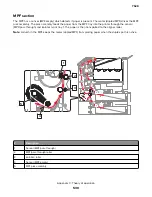
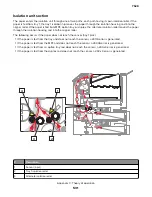
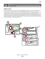
Duplex feed roller
8
Sensor (duplex staging)
9
Duplex aligner roller
10
Sensor (duplex entry)
Print engine theory
Electrophotographic process
The method that all laser and LED printers use to print is called the electrophotographic (EP) process. These
machines use differences in charge to manipulate and move toner from the print cartridge to the printed page.
Even though the basic EP process is the same for every laser and LED printer, the specifics for each printer are
different.
EP process basics
This printer is a four-laser tandem color laser printer that uses four print cartridges (cyan, yellow, magenta, and
black) to create text and images on paper.
The printer has a black imaging unit including a developer unit and a photoconductor drum. It also has a color
imaging kit including three separate color developers and a combined photoconductor unit with three
photoconductor drums.
During the printing process, the printer follows the six basic EP process steps to create its output to the page.
1
Charge the photoconductor.
2
Expose the photoconductor with the laser.
3
Develop toner on the photoconductor.
4
First transfer to the transfer module , and second transfer to the paper.
5
Fuse the toner to the paper.
6
Clean/Erase the photoconductor and the transfer module.
In summary, the printer controller board receives print data and print command. The controller board then
initiates the print process. The controller board is the command center for the EP process and coordinates the
various motors and signals.
The high-voltage power supply (HVPS) sends charge to various components in the EP process. The laser fires
on the photoconductors and alters the surface charge relative to the planed image for each photoconductor.
Each photoconductor rotates past its respective developer roll, and toner is developed on the surface of each
photoconductor. The four separate color images are then transferred to the transfer belt on the transfer module
as it passes under the photoconductors. After the image is transferred to the transfer belt, the photoconductors
are cleaned and recharged.
7528
Appendix C: Theory of operation
537
Summary of Contents for XC4150
Page 34: ...7528 34 ...
Page 276: ...7528 276 ...
Page 294: ...Scan SE Scanner Info 7528 Service menus 294 ...
Page 317: ...3 Remove the screw B from the lower left side of the cover B 7528 Repair information 317 ...
Page 320: ...3 Remove the three screws A 7528 Repair information 320 ...
Page 327: ...3 Remove the E clip B 4 Remove the E clip C 7528 Repair information 327 ...
Page 358: ...5 Remove the two screws D from under the gear box 7528 Repair information 358 ...
Page 360: ...3 Disconnect the cable A from the LVPS 7528 Repair information 360 ...
Page 370: ...3 Disconnect the motor cable A A 7528 Repair information 370 ...
Page 371: ...4 Remove the four screws B and then remove the motor B 7528 Repair information 371 ...
Page 374: ...4 Disconnect the cable B 5 Remove the screw C securing the HVPS C 7528 Repair information 374 ...
Page 400: ...14 Remove the clip M and then remove the spacer 7528 Repair information 400 ...
Page 403: ...7528 Repair information 403 ...
Page 414: ...5 Remove the screw C from the printhead 7528 Repair information 414 ...
Page 429: ...8 Route the ADF cable through the flatbed 9 Remove the ADF 7528 Repair information 429 ...
Page 437: ...7 Disconnect the two cables B on the controller board 7528 Repair information 437 ...
Page 443: ...5 Remove the screw D and then remove the scanner tilt D 7528 Repair information 443 ...
Page 478: ...7528 478 ...
Page 485: ...7528 485 ...
Page 487: ...Assembly 1 Covers 1 2 4 6 7 8 9 1 14 10 3 5 13 13 11 11 12 7528 Parts catalog 487 ...
Page 489: ...Assembly 2 Covers 2 14 7528 Parts catalog 489 ...
Page 491: ...Assembly 3 Control panel 5 4 3 2 1 7528 Parts catalog 491 ...
Page 493: ...Assembly 4 ADF and flatbed 1 3 11 10 4 9 5 6 7 8 2 7528 Parts catalog 493 ...
Page 495: ...Assembly 5 Fuser 1 7528 Parts catalog 495 ...
Page 497: ...Assembly 6 Transfer module 1 2 7528 Parts catalog 497 ...
Page 499: ...Assembly 7 Paper feed 8 2 1 2 4 7 3 5 5 6 7528 Parts catalog 499 ...
Page 501: ...Assembly 8 Paper path 1 8 6 2 3 1 10 5 7 9 4 7528 Parts catalog 501 ...
Page 503: ...Assembly 9 Paper path 2 1 4 2 5 10 3 6 9 7 8 7528 Parts catalog 503 ...
Page 505: ...Assembly 10 Duplex 9 8 3 3 7 6 1 1 2 4 5 7528 Parts catalog 505 ...
Page 507: ...Assembly 11 Electrical 16 2 3 4 5 7 8 9 11 12 13 15 6 1 14 10 7528 Parts catalog 507 ...
Page 510: ...7528 Parts catalog 510 ...
Page 511: ...Assembly 12 550 sheet tray option 1 2 1 7528 Parts catalog 511 ...
Page 513: ...Assembly 13 550 sheet tray option 2 1 2 3 4 12 11 6 13 5 9 10 7 8 7528 Parts catalog 513 ...
Page 515: ...Assembly 14 Adjustable stand 2 2 3 3 1 7528 Parts catalog 515 ...
Page 518: ...7528 Parts catalog 518 ...
Page 520: ...7528 520 ...
Page 527: ...3 Apply the changes 7528 Appendix B Options and features 527 ...
Page 528: ...7528 528 ...
Page 554: ...7528 554 ...
Page 568: ...7528 Part number index 568 ...
Page 574: ...7528 Part name index 574 ...

