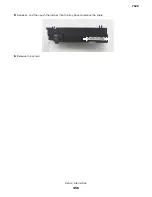


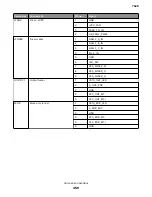

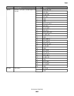
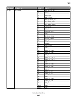

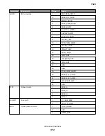


Connector
Connects to
Pin no.
Signal
JWT1
Waste toner
1
SENSE
2
WT_VREF
3
VAC
4
GND
JISP1
ISP connector
1
GND
2
3
USBOUT-
4
GND
5
US
6
USB_HD1_D-
7
GND
8
+3.3V
9
ISP_RST_R
10
+5V_RIP
11
I2C_DAT_ISP_L
12
+5V_RIP
13
I2C_CLK_ISP_L
14
+5V_RIP
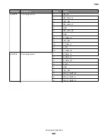
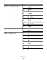
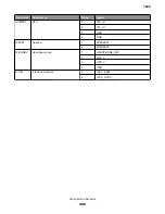
J61
Hard drive
JCTM1
TMC
1
+5V_SW
2
-CART_METER_C_IN
3
-CART_METER_M_IN
4
-CART_METER_Y_IN
5
-CART_METER_K_IN
6
GND
JSNS1
Bin full / duplex entry sensor
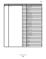
JMIRR1
Mirror motor
1
MM_REF_CLKC
2
MM_LOCK_IN
3
MM_START_OUT
4
GND
5
V25_MM_25V
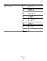
JPFUSB1
USB port
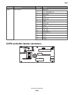
7528
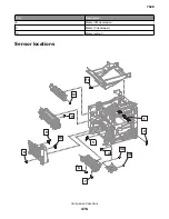
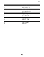
Component locations
466
Summary of Contents for XC4150
Page 34: ...7528 34 ...
Page 276: ...7528 276 ...
Page 294: ...Scan SE Scanner Info 7528 Service menus 294 ...
Page 317: ...3 Remove the screw B from the lower left side of the cover B 7528 Repair information 317 ...
Page 320: ...3 Remove the three screws A 7528 Repair information 320 ...
Page 327: ...3 Remove the E clip B 4 Remove the E clip C 7528 Repair information 327 ...
Page 358: ...5 Remove the two screws D from under the gear box 7528 Repair information 358 ...
Page 360: ...3 Disconnect the cable A from the LVPS 7528 Repair information 360 ...
Page 370: ...3 Disconnect the motor cable A A 7528 Repair information 370 ...
Page 371: ...4 Remove the four screws B and then remove the motor B 7528 Repair information 371 ...
Page 374: ...4 Disconnect the cable B 5 Remove the screw C securing the HVPS C 7528 Repair information 374 ...
Page 400: ...14 Remove the clip M and then remove the spacer 7528 Repair information 400 ...
Page 403: ...7528 Repair information 403 ...
Page 414: ...5 Remove the screw C from the printhead 7528 Repair information 414 ...
Page 429: ...8 Route the ADF cable through the flatbed 9 Remove the ADF 7528 Repair information 429 ...
Page 437: ...7 Disconnect the two cables B on the controller board 7528 Repair information 437 ...
Page 443: ...5 Remove the screw D and then remove the scanner tilt D 7528 Repair information 443 ...
Page 478: ...7528 478 ...
Page 485: ...7528 485 ...
Page 487: ...Assembly 1 Covers 1 2 4 6 7 8 9 1 14 10 3 5 13 13 11 11 12 7528 Parts catalog 487 ...
Page 489: ...Assembly 2 Covers 2 14 7528 Parts catalog 489 ...
Page 491: ...Assembly 3 Control panel 5 4 3 2 1 7528 Parts catalog 491 ...
Page 493: ...Assembly 4 ADF and flatbed 1 3 11 10 4 9 5 6 7 8 2 7528 Parts catalog 493 ...
Page 495: ...Assembly 5 Fuser 1 7528 Parts catalog 495 ...
Page 497: ...Assembly 6 Transfer module 1 2 7528 Parts catalog 497 ...
Page 499: ...Assembly 7 Paper feed 8 2 1 2 4 7 3 5 5 6 7528 Parts catalog 499 ...
Page 501: ...Assembly 8 Paper path 1 8 6 2 3 1 10 5 7 9 4 7528 Parts catalog 501 ...
Page 503: ...Assembly 9 Paper path 2 1 4 2 5 10 3 6 9 7 8 7528 Parts catalog 503 ...
Page 505: ...Assembly 10 Duplex 9 8 3 3 7 6 1 1 2 4 5 7528 Parts catalog 505 ...
Page 507: ...Assembly 11 Electrical 16 2 3 4 5 7 8 9 11 12 13 15 6 1 14 10 7528 Parts catalog 507 ...
Page 510: ...7528 Parts catalog 510 ...
Page 511: ...Assembly 12 550 sheet tray option 1 2 1 7528 Parts catalog 511 ...
Page 513: ...Assembly 13 550 sheet tray option 2 1 2 3 4 12 11 6 13 5 9 10 7 8 7528 Parts catalog 513 ...
Page 515: ...Assembly 14 Adjustable stand 2 2 3 3 1 7528 Parts catalog 515 ...
Page 518: ...7528 Parts catalog 518 ...
Page 520: ...7528 520 ...
Page 527: ...3 Apply the changes 7528 Appendix B Options and features 527 ...
Page 528: ...7528 528 ...
Page 554: ...7528 554 ...
Page 568: ...7528 Part number index 568 ...
Page 574: ...7528 Part name index 574 ...


