background image

4

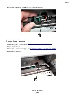
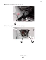
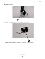
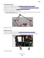
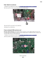
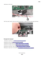
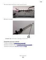
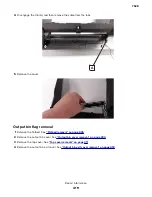
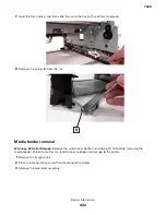
Remove the screw (A).

5

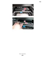
Remove the retainer (B), and then remove the sensor from the bracket.

Installation note: 

Use the retainer of the old sensor when installing the new sensor.

7528

Repair information

407

Summary of Contents for XC4150

Page 1: ...CX725 and XC4150 7528 576 578 598 Service Manual Start diagnostics Maintenance Safety and notices Trademarks Index January 25 2016 www lexmark com P N 12G3423 ...

Page 2: ... functionally equivalent product program or service that does not infringe any existing intellectual property right may be used instead Evaluation and verification of operation in conjunction with other products programs or services except those expressly designated by the manufacturer are the user s responsibility Trademarks Lexmark and the Lexmark logo are trademarks of Lexmark International Inc ...

Page 3: ...læring 14 Laser Hinweis 15 Laserilmoitus 15 Lasermerknad 15 Meddelande om laser 15 レーザーについて 16 레이저 고지사항 16 激光注意事项 16 雷射聲明 16 Safety information 16 Consignes de sécurité 17 Informació de seguretat 17 Información de seguridad 18 Informações sobre segurança 18 Informatie over veiligheid 18 Informazioni sulla sicurezza 19 Säkerhetsinformation 19 Sicherheitshinweise 20 Sikkerhedsoplysninger 20 Sikkerhe...

Page 4: ...6 Initial print quality check 36 Toner easily rubs off check 36 Background or gray background check 38 Blank or white pages check 39 Gapping or half color page check 41 Blurred print or color misalignment check 42 Horizontal colored lines or banding check 43 Text or images cut off check 45 Mottled print and dots check 45 Vertical white lines check 46 Ghost images check 48 Solid color or black imag...

Page 5: ...4 221 paper jams 95 230 paper jams 96 231 paper jams 102 232 paper jams 108 240 paper jams 113 241 paper jams 125 242 244 paper jams 133 28y and 680 paper jams 158 User attendance messages 163 31 user attendance error messages 163 32 user attendance error messages 164 33 user attendance error messages 165 42 user attendance error messages 165 43 user attendance error messages 166 80 user attendanc...

Page 6: ... failure service check 239 Scanner configuration error service check 240 Scan fax copy symptoms 240 Black or blank page copy service check 241 Flatbed motor service check 242 Flatbed home position service check 242 ADF rattling noise service check 243 Flatbed legal size scan service check 244 ADF feed errors service check 245 ADF duplex service check 247 Modem fax card service check 248 Blank space...

Page 7: ...282 Printer Setup 282 Printer diagnostics and adjustments 284 Scanner Diagnostics 286 Additional input tray diagnostics 290 Service Engineer menu 291 Entering Invalid engine mode 291 Entering the Service Engineer SE menu 291 General SE 291 Network SE 291 Fax SE 292 Scan SE 293 Repair information 295 Removal precautions 295 Data security notice 295 Handling ESD sensitive parts 296 Controller board ...

Page 8: ... removal 335 External air filter removal 336 Control panel removals 336 Lower control panel bezel removal 336 Control panel bezel removal 337 Control panel removal 337 Control panel tub removal 338 Control panel tub mounting bracket removal 339 Control panel arms removal 340 Duplex removals 343 Duplex inner guide removal 343 Duplex outer guide removal 344 Pivot shaft removal 345 Tensioner belt remo...

Page 9: ...r removal 387 Transfer module removal 388 Transfer module guide rail removal 390 Sensor media type removal 394 Sensor input removal 395 Deskew rollers removal 396 Diverter removal 404 Redrive guide removal 406 Sensor redrive removal 406 Rear removals 408 Controller board shield removal 408 Inner controller board shield removal 409 Controller board removal 409 TPS cables removal 411 Modem removal 4...

Page 10: ...7 Sensor 550 sheet tray pass through removal 448 Sensor 550 sheet tray trailing edge removal 449 Sensor 550 sheet tray paper size removal 449 550 sheet tray controller board assembly removal 451 550 sheet tray interface cable removal 452 550 sheet tray empty sensor actuator removal 453 Sensor 550 sheet tray empty removal 454 Sensor 550 sheet tray index removal 455 Component locations 457 Printer c...

Page 11: ...Electrical 507 Assembly 12 550 sheet tray option 1 511 Assembly 13 550 sheet tray option 2 513 Assembly 14 Adjustable stand 515 Assembly 15 Miscellaneous parts 517 Assembly 16 Power cords 519 Appendix A Printer specifications 521 Power consumption 521 Product power consumption 521 Sleep Mode 521 Hibernate Mode 521 Off mode 522 Total energy usage 522 Selecting a location for the printer 522 Noise em...

Page 12: ... Print engine theory 537 Electrophotographic process 537 EP process basics 537 ADF theory 544 ADF paper path 545 ADF paper path sensors 546 ADF tray pick and feed 546 ADF separation 547 ADF registration 548 ADF scan and exit 549 ADF duplex 550 Color theory 551 Color theory 551 Appendix D Acronyms 555 Acronyms 555 Index 557 Part number index 563 Part name index 569 7528 Table of contents 12 ...

Page 13: ...nte ont été conçus de manière à ce que personne ne soit jamais exposé à des radiations laser dépassant le niveau de classe I dans le cadre d un fonctionnement normal de l entretien par l utilisateur ou de la maintenance Notificació del làser La impressora està certificada als EUA per complir els requeriments de DHHS 21 CFR capítol I subcapítol J per a productes de làser Classe I 1 i a la resta del m...

Page 14: ...ghezza d onda dei 650 670 nanometri e contenuto in un gruppo testina di stampa non riparabile Il sistema laser e la stampante sono stati progettati in modo da impedire l esposizione a radiazioni laser superiori al livello previsto dalla Classe I durante le normali operazioni di stampa manutenzione o assistenza Laserinformatie De printer is in de Verenigde Staten gecertificeerd als een product dat v...

Page 15: ...illa ja joka on suljettu tulostuspäähän jota käyttäjä ei voi huoltaa Laserjärjestelmä ja tulostin ovat rakenteeltaan sellaisia että käyttäjä ei joudu alttiiksi luokkaa 1 suuremmalle säteilylle normaalin käytön ylläpidon tai huollon aikana Lasermerknad Skriveren er sertifisert i USA for samsvar med kravene i DHHS 21 CFR kapittel I underkapittel J for laserprodukter av klasse I 1 og er andre steder s...

Page 16: ...为分类 I 激光产品不具有危险性 本打印机内部含有分类 IIIb 3b 的磷化铝镓铟激光 标称值为 15 毫瓦 其工作波长范围在 650 670nm 之间 并被封闭在不可维修的打印头配件中 本激光系统及打印机的 设计 在一般操作 使用者维护或规定内的维修情况下 不会使人体接触分类 I 以上等级的辐射 雷射聲明 本印表機係經過美國核可 符合 DHHS 21 CFR Chapter I Subchapter J 規定的 I 1 級雷射產品 在美國 以外的地區 為符合 IEC 60825 1 規定的 I 級雷射產品 根據 I 級雷射產品的規定 這類產品不會對人體造成傷害 本印表機所採用之 IIIb 3b 級 AlGaInP 雷射在 650 至 670 奈米 nanometer 波長範圍內運作時通常為 15 毫瓦特 milliwatt 且含括在不可修復列印頭組件中 使 用者只要以正確的方法操作及維...

Page 17: ... ATTENTION RISQUE DE BLESSURE La batterie lithium de ce produit n est pas destinée à être remplacée Si vous ne respectez pas les instructions de remplacement de la batterie vous risquez de provoquer une explosion Ne rechargez pas ne désassemblez pas et ne brûlez pas la batterie au lithium Mettez les batteries lithium usagées au rebut selon les instructions du fabricant et les réglementations local...

Page 18: ...autorizado de peças de substituição As informações sobre manutenção deste produto foram preparadas para utilização por um técnico profissional experiente e não se destinam ao uso por outros Pode haver maior risco de choque elétrico e danos pessoais durante a desmontagem e manutenção deste produto Os técnicos profissionais experientes devem entender esses riscos e tomar as precauções necessárias ATEN...

Page 19: ...e nell area del prodotto in cui si lavora Scollegare l alimentazione prima di iniziare o prestare la massima attenzione se per effettuare l operazione il prodotto deve ricevere l alimentazione ATTENZIONE PERICOLO DI LESIONI La batteria al litio contenuto nel prodotto non deve essere sostituita in caso di sostituzione errata della batteria al litio potrebbe verificarsi un esplosione Non ricaricare s...

Page 20: ... oprindelige design og specifikke komponenter Producenten er ikke ansvarlig for sikkerhed i tilfælde af brug af uautoriserede dele til udskiftning Vedligeholdelsesoplysninger om dette produkt er udarbejdet til brug af en kvalificeret servicetekniker og er ikke beregnet til at blive brugt af andre Der kan være en forøget risiko for elektrisk stød eller personskade ved afmontering og service af dette ...

Page 21: ...lä tavalla VAARA SÄHKÖISKUN VAARA Tämä symboli ilmaisee että tuotteen työskentelyalueella on olemassa vaarallinen jännite Irrota laite verkkovirrasta ennen kuin aloitat tai toimi erittäin varovasti jos laitteessa on oltava virta työn aikana VAARA LOUKKAANTUMISVAARA Tuotteessa olevaa litiumakkua ei ole tarkoitettu vaihdettavaksi Litiumakun poistaminen väärin aiheuttaa räjähdysvaaran Älä lataa pura ...

Page 22: ...業を始める前に 製品から電源コードを取り外してください また作業時に 製品に給電する必要がある 場合は 十分に注意するようにしてください 危険 ケガの恐れあり この製品に使用されているリチウム電池は 交換を前提としていません リチウム電 池の交換を誤ると破裂する危険性があります リチウム電池の充電 解体 焼却はしないでください 使用済 みのリチウム電池を廃棄する際は 製造元の指示およびお使いの地域の法律に従ってください 安全資訊 本產品安全性係以原始設計及特定元件之測試與核准為依據 如有使用未獲授權替換組件之情形者 製造 商對安全性概不負責 本產品之維護資訊僅供專業維修人員使用 而非預定由他人使用 拆裝及維修本產品時 有可能造成電擊與人員損傷之危險 專業維修人員應瞭解前項危險並採取必要措施 請當心 有觸電的危險 當您看到此符號時 表示您所在產品工作區有危險電壓 開始工作之前 請先 拔掉產品...

Page 23: ...ix A Printer specifications contains detailed specifications of the product Appendix B Options and features contains the available options and other features of the product Appendix C Theory of operation contains the theory on how the printer operates Appendix D Acronyms contains a list of acronyms in the manual and their meanings Conventions Note A note identifies information that could help you War...

Page 24: ...ices The power capacity of these types of accessories can be easily overloaded by a laser printer and may result in a risk of fire property damage or poor printer performance CAUTION POTENTIAL INJURY Only a Lexmark Inline Surge Protector that is properly connected between the printer and the power cord provided with the printer may be used with this product The use of non Lexmark surge protection d...

Page 25: ...reen display duplex print duplex scan networking hard disk CX725de 7 in color touch screen display duplex print duplex scan networking 7528 576 XC4150 7 in color touch screen display duplex print duplex scan networking hard disk 7528 598 For information on diagnosing a problem see Diagnostic information on page 35 For information on removing and reinstalling parts see Repair information on page 29...

Page 26: ... paper between 100 and 200 Sheffield points Moisture content The amount of moisture in paper affects both print quality and the printer ability to feed the paper correctly Leave paper in its original wrapper until you use it Exposure of paper to moisture changes can degrade its performance Store paper in its original wrapper in the same environment as the printer for 24 to 48 hours before printing...

Page 27: ... individual packages on a flat surface Do not store anything on top of individual paper packages Take paper out of the carton or wrapper only when you are ready to load it in the printer The carton and wrapper help keep the paper clean dry and flat Using specialty media Tips on using envelopes From the printer control panel set the paper size type texture and weight in the Paper menu to match the en...

Page 28: ...labels to peel off during printing resulting in a jam Partial sheets also contaminate the printer and the cartridge with adhesive and could void the printer and toner cartridge warranties Before loading labels on the tray flex and fan labels to loosen them Straighten the edges on a level surface Tips on using card stock Card stock is heavy single ply specialty media Many of its variable characteris...

Page 29: ...x 13 4 in 3 x 52 76 2 x 127 mm 3 x 5 in X X 4 x 52 101 6 x 127 mm 4 x 5 in X X Statement 140 x 216 mm 5 5 x 8 5 in Executive 184 x 267 mm 7 3 x 10 5 in Letter 216 x 279 mm 8 5 x 11 in Folio 216 x 330 mm 8 5 x 13 in Legal 216 x 356 mm 8 5 x 14 in DL Envelope 110 x 220 mm 4 3 x 8 7 in X C5 Envelope 162 x 229 mm 6 4 x 9 in X B5 Envelope 176 x 250 mm 6 9 x 9 8 in X 7 3 4 Envelope 98 x 191 mm 3 9 x 7 5...

Page 30: ... Off Note Banner is supported in the multipurpose feeder only if width up to 215 9 mm 8 5 in and length to 1320 8 mm 52 in Make sure the paper size setting is set Universal Paper sizes supported by the ADF and scanner glass Paper size Dimensions ADF Scanner glass Letter 216 x 279 mm 8 5 x 11 in Executive 184 x 267 mm 7 3 x 10 5 in Legal 216 x 356 mm 8 5 x 14 in A4 210 x 297 mm 8 3 x 11 7 in A5 148...

Page 31: ... Plain Paper1 Card Stock2 Glossy1 Labels Paper1 Vinyl Envelopes Light Paper1 Heavy Paper1 1 Supported for two sided printing 2 Supported for two sided printing only up to 162 g m2 90 lb index Data security notice Identifying printer memory Volatile memory The printer uses standard random access memory RAM to buffer user data temporarily during simple print and copy jobs Non volatile memory The pri...

Page 32: ...the printer To erase non volatile memory 1 From the home screen touch Settings Device Maintenance Out of Service Erase 2 Select the Sanitize all information on nonvolatile memory check box and then touch ERASE 3 Follow the instructions on the display To erase the hard disk memory 1 From the home screen touch Settings Device Maintenance Out of Service Erase 2 Select the Sanitize all information on ...

Page 33: ...tters Spring hook Feeler gauges Analog or digital multimeter Parallel wrap plug 1319128 Twinax serial debug cable 1381963 Coax serial debug cable 1381964 Flash light optional 3 mm hex wrench 7528 General information 33 ...

Page 34: ...7528 34 ...

Page 35: ...g the initial troubleshooting check With the power cord unplugged from the electrical outlet check if the cord is free from breakage short circuits disconnected wires or incorrect connections Make sure that the printer is properly grounded Make sure that the power supply line voltage is within 10 of the rated line voltage Make sure that the printer is securely installed on a level surface in a wel...

Page 36: ...are properly set and locked From the control panel set the paper size and type to match the paper loaded in the tray Print and keep the menu settings page The original menu settings page will be used to restore the custom settings if necessary Make sure that the Print resolution and Toner darkness on the menu settings page are set to their default values Check the toner cartridge for damage and re...

Page 37: ... problem is solved Step 5 Remove and then reinstall the fuser See Fuser removal on page 387 Does the problem remain Go to step 6 The problem is solved Step 6 Replace the fuser See Fuser removal on page 387 Does the problem remain Go to step 7 The problem is solved Step 7 a From the home screen touch Settings Device Maintenance Configuration Menu Reports Event Log b Check the log history for fuser e...

Page 38: ...magenta or yellow then replace the developer unit of the affected color If the affected color is black then replace the imaging unit Does the problem remain Go to step 4 The problem is solved Step 4 Replace the imaging kit Does the problem remain Go to step 5 The problem is solved Step 5 Reseat the HVPS cable on the HVPS and on the JHVPS1 connector on the controller board Does the problem remain G...

Page 39: ...ure all the packing materials on the imaging unit are removed Does the problem remain Go to step 2 The problem is solved Step 2 a Enter the Diagnostics menu and then navigate to Advanced Print Quality Samples Advanced Print Quality Samples b Check the test page Is only one color missing Go to step 3 Go to step 5 Step 3 Check the contacts between the imaging unit and developer unit of the affected ...

Page 40: ...age 350 Does the problem remain Go to step 8 The problem is solved Step 8 a Manually turn the motor b While turning the motor check if the couplers that drive the imaging kit move Do the couplers move Go to step 10 Go to step 9 Step 9 Replace the EP gear box See EP gear box removal on page 356 Does the problem remain Go to step 10 The problem is solved Step 10 Check if the pins on the HVPS freely ...

Page 41: ...sure all the packing materials on the imaging unit are removed Does the problem remain Go to step 2 The problem is solved Step 2 a Reseat the cyan magenta and yellow developer units in the imaging kit b Reseat the imaging kit c Enter the Diagnostics menu and then navigate to Advanced Print Quality Samples Advanced Print Quality Samples d Check the test page Does the problem remain Go to step 3 The...

Page 42: ...e to Advanced Print Quality Samples Advanced Print Quality Samples b Check the test page Is only one color blurred or misaligned Go to step 3 Go to step 6 Step 3 If the affected color is cyan magenta or yellow then replace the developer unit of the affected color If the affected color is black then reseat the imaging unit Does the problem remain Go to step 4 The problem is solved Step 4 Perform th...

Page 43: ...ep 10 Step 9 Clean the lenses and then reinstall the printhead Does the problem remain Go to step 10 The problem is solved Step 10 Replace the EP gear box See EP gear box removal on page 356 Does the problem remain Go to step 11 The problem is solved Step 11 Replace the printhead See Printhead removal on page 413 Does the problem remain Go to step 12 The problem is solved Step 12 Replace the contr...

Page 44: ...lines appear on the same area of the page Do the lines appear on the same area Go to step 4 Go to step 5 Step 4 Perform the repeating defects check See Repeating defects check on page 57 Does the problem remain Go to step 5 The problem is solved Step 5 Check the pages right after the defective page Do the lines appear after two consecutive normal pages were printed Go to step 6 The problem is solv...

Page 45: ...roblem is solved Mottled print and dots check Action Yes No Step 1 a From the home screen touch Settings Device Preferences b Check if the paper type and size settings match the paper type and size set on the tray Do the settings match Go to step 3 Go to step 2 Step 2 Change the paper size and type or adjust the size settings in the tray Does the problem remain Go to step 3 The problem is solved S...

Page 46: ...the affected color is black then replace the imaging unit Does the problem remain Go to step 8 The problem is solved Step 8 Check if the affected color is black Is the affected color black Go to step 10 Go to step 9 Step 9 Replace the photoconductor unit Does the problem remain Go to step 10 The problem is solved Step 10 Check the transfer module for proper installation and damage and replace if n...

Page 47: ...of support Go to step 4 Step 4 Replace the photoconductor unit Does the problem remain Contact the next level of support The problem is solved Step 5 Check the transfer module for proper installation and damage and replace if necessary See Transfer module removal on page 388 Does the problem remain Go to step 6 The problem is solved Step 6 Clean the printhead See Cleaning the printhead lenses on p...

Page 48: ...ce the imaging unit Does the problem remain Go to step 4 The problem is solved Step 4 a Check if the ghost image is colored or black b Measure the distance from one point of the original image to the same point on the ghost image Is the distance 94 2 mm Go to step 5 Go to step 6 Step 5 If the ghost image is colored then replace the color photoconductor unit If the ghost image is black then replace...

Page 49: ... Go to step 3 Step 2 Replace the imaging unit Does the problem remain Go to step 4 The problem is solved Step 3 Replace the photocunductor unit Does the problem remain Go to step 4 The problem is solved Step 4 a Place a narrow strip of paper over the gap between the developers Note Make sure that the paper stays in place when reinstalling the imaging unit to prevent the laser from discharging the ...

Page 50: ... check the continuity of the HVPS cable Does the cable have continuity Go to step 9 Go to step 8 Step 8 Replace the HVPS cable Does the problem remain Go to step 9 The problem is solved Step 9 Replace the HVPS See HVPS removal on page 373 Does the problem remain Go to step 10 The problem is solved Step 10 Replace the printhhead See Printhead removal on page 413 Does the problem remain Contact the ...

Page 51: ...Go to step 4 The problem is solved Step 4 Replace the transfer module See Transfer module removal on page 388 Does the problem remain Go to step 5 The problem is solved Step 5 Replace the fuser See Fuser removal on page 387 Does the problem remain Contact the next level of support The problem is solved Image void scan direction check Action Yes No Step 1 Load paper from a fresh package Note Paper ...

Page 52: ...the interval between every defect Does the defect occur in 55 mm intervals Contact the next level of support Go to step 7 Step 7 Check the HVPS cable for proper connection and damage and replace if necessary Does the problem remain Go to step 8 The problem is solved Step 8 Replace the HVPS See HVPS removal on page 373 Does the problem remain Go to step 9 The problem is solved Step 9 Replace the co...

Page 53: ... Step 4 Check the developer hold downs for damage or loose springs and replace if necessary See Developer hold down removal on page 415 Does the problem remain Go to step 5 The problem is solved Step 5 Check for missing colors Is only one color missing Go to step 8 Go to step 6 Step 6 Check the printhead for dust or debris Is the printhead free of dust or debris Go to step 8 Go to step 7 Step 7 Re...

Page 54: ...Quality b Check the Toner darkness setting value Is the darkness setting too high Go to step 2 Go to step 3 Step 2 Adjust the darkness setting to the proper value Does the problem remain Go to step 3 The problem is solved Step 3 Reseat the imaging kit and then perform a print job Does the problem remain Go to step 4 The problem is solved Step 4 a Enter the Diagnostics menu and then navigate to Adv...

Page 55: ... remain Go to step 8 The problem is solved Step 8 Replace the imaging kit Does the problem remain Go to step 9 The problem is solved Step 9 Replace the HVPS See HVPS removal on page 373 Does the problem remain Go to step 10 The problem is solved Step 10 Replace the controller board See Controller board removal on page 409 Does the problem remain Contact the next level of support The problem is sol...

Page 56: ...the toner cartridge contacts for damage and replace if necessary See Toner cartridge contacts removal on page 382 Does the problem remain Go to step 6 The problem is solved Step 6 Replace the HVPS See HVPS removal on page 373 Does the problem remain Go to step 7 The problem is solved Step 7 Replace the controller board See Controller board removal on page 409 Does the problem remain Contact the ne...

Page 57: ...The problem is solved Step 6 Replace the fuser See Fuser removal on page 387 Does the problem remain Go to step 7 The problem is solved Step 7 Replace the LVPS See LVPS removal on page 359 Does the problem remain Contact the next level of support The problem is solved Repeating defects check Action Yes No Step 1 Check the printer rollers for dust or debris Are the rollers free of dust or debris Go...

Page 58: ...t level of support The problem is solved Step 7 Measure the distance between the repeating marks Is the distance between the marks either 34 6 mm 95 mm or 110 mm Go to step 8 Go to step 9 Step 8 Replace the fuser See Fuser removal on page 387 Does the problem remain Contact the next level of support The problem is solved Step 9 Measure the distance between the repeating marks Is the distance betwe...

Page 59: ...ragments Does the problem remain Go to step 5 The problem is solved Step 5 Check the transfer module for debris and fragments Is the transfer module free of debris and fragments Contact the next level of support Go to step 6 Step 6 Remove the debris and fragments Does the problem remain Contact the next level of support The problem is solved Light print check Action Yes No Step 1 a From the home s...

Page 60: ...oblem is solved Step 6 Check the cartridge toner level Is the cartridge empty Go to step 7 Go to step 8 Step 7 Replace the toner cartridge Does the problem remain Go to step 8 The problem is solved Step 8 Remove and then reinstall the developer unit of the affected color Does the problem remain Go to step 9 The problem is solved Step 9 a Enter the Diagnostics menu and then navigate to Printer diag...

Page 61: ... the cable properly connected at both ends Go to step 16 Go to step 15 Step 15 Reconnect the cable Does the problem remain Go to step 16 The problem is solved Step 16 Check the cable for continuity Does the cable have continuity Go to step 18 Go to step 17 Step 17 Replace the HVPS cable Does the problem remain Go to step 18 The problem is solved Step 18 Check the toner cartridge contacts for damag...

Page 62: ...ary Does the problem remain Go to step 2 The problem is solved Step 2 a From the home screen touch Settings Device Preferences b Check if the paper type and size settings match the paper type and size set on the tray Do the settings match Go to step 4 Go to step 3 Step 3 Change the paper size and type or adjust the size settings in the tray Does the problem remain Go to step 4 The problem is solve...

Page 63: ...he cable on the JMTR1 connector on the controller board for proper connection and damage and replace if necessary Does the problem remain Go to step 10 The problem is solved Step 10 Replace the motor deskew See Motor deskew removal on page 353 Does the problem remain Go to step 11 The problem is solved Step 11 Check the condition of the deskew rollers Are the rollers free from excess wear contamin...

Page 64: ...ep 3 The problem is solved Step 3 Check the large and small platen glasses on the flatbed scanner for contamination Are the platen glasses free of contamination Go to step 5 Go to step 4 Step 4 Clean both sides of the platen glasses Does the problem remain Go to step 5 The problem is solved Step 5 Check the white reference strip on the bottom of the ADF float plate for contamination Are the referenc...

Page 65: ...dentify and then resolve the print quality defect See Fixing print quality issues on page 36 Does the problem remain Go to step 3 The problem is solved Step 3 Check the small platen glass on the flatbed scanner for contamination or damage Is the platen glass free of contamination and damage Go to step 5 Go to step 4 Step 4 Clean the glass or replace the ADF top cover Does the problem remain Go to s...

Page 66: ...t quality samples Go to step 2 Go to step 3 Step 2 Identify and then resolve the print quality defect See Fixing print quality issues on page 36 Does the problem remain Go to step 3 The problem is solved Step 3 Check the large platen glass on the scanner unit assembly for contamination or damage Is the glass free of contamination and damage Go to step 5 Go to step 4 Step 4 a Clean the platen glass...

Page 67: ...and then resolve the print quality defect See Fixing print quality issues on page 36 Does the problem remain Go to step 3 The problem is solved Step 3 Check if the printer is placed on a flat sturdy and stable surface Is the printer on a flat sturdy and stable surface Go to step 5 Go to step 4 Step 4 Place the printer on a flat sturdy and stable surface Does the problem remain Go to step 5 The proble...

Page 68: ... Configuration ADF Deskew ADF Electronic Deskew On Does the problem remain Go to step 10 The problem is solved Step 10 Check the ADF pick roller assembly for wear or damage Is the assembly free of wear or damage Go to step 12 Go to step 11 Step 11 Replace the ADF pick roller assembly Does the problem remain Go to step 12 The problem is solved Step 12 Check the ADF separator roller for wear or damag...

Page 69: ...ved Step 3 Properly load the document into the ADF tray and ensure that all guides are correctly set Does the problem remain Go to step 4 The problem is solved Step 4 Clear the paper path in the ADF of any obstructions Does the problem remain Go to step 5 The problem is solved Step 5 Open and then properly close the following ADF top cover Does the problem remain Go to step 6 The problem is solved...

Page 70: ...height is below the maximum paper fill indicator Do not slide paper into the tray Load paper as shown in the illustration Make sure that the paper guides are positioned correctly and are not pressing tightly against the paper or envelopes Push the tray firmly into the printer after loading paper Use recommended paper Use only recommended paper or specialty media Do not load paper that is wrinkled cr...

Page 71: ...e paper according to manufacturer recommendations Identifying jam locations Notes When Jam Assist is set to On the printer flushes blank pages or pages with partial prints after a jammed page has been cleared Check your printed output for blank pages When Jam Recovery is set to On or Auto the printer reprints jammed pages Jam locations 1 Standard bin 2 Automatic document feeder ADF 3 Fuser 4 Trays ...

Page 72: ... sensor inside the optional tray is easily damaged by static electricity Touch a metal surface before removing the jammed paper in the tray 2 Remove the jammed paper Note Make sure that all paper fragments are removed 3 Insert the tray 7528 Diagnostic information 72 ...

Page 73: ...Make sure that all paper fragments are removed 3 Close door E Paper jam in the multipurpose feeder 1 Remove paper from the multipurpose feeder 2 Pull out the tray 3 Remove the jammed paper Note Make sure that all paper fragments are removed 7528 Diagnostic information 73 ...

Page 74: ... sure that all paper fragments are removed 2 Open doors A and D and then remove any paper fragments CAUTION HOT SURFACE The inside of the printer might be hot To reduce the risk of injury from a hot component allow the surface to cool before touching it 7528 Diagnostic information 74 ...

Page 75: ...n door A CAUTION HOT SURFACE The inside of the printer might be hot To reduce the risk of injury from a hot component allow the surface to cool before touching it 2 Remove the jammed paper Note Make sure that all paper fragments are removed 7528 Diagnostic information 75 ...

Page 76: ...3 Open the fuser access door 4 Remove the jammed paper Note Make sure that all paper fragments are removed 5 Close door A 7528 Diagnostic information 76 ...

Page 77: ...rinter might be hot To reduce the risk of injury from a hot component allow the surface to cool before touching it 2 Open the duplex cover 3 Remove the jammed paper Note Make sure that all paper fragments are removed 4 Close the duplex cover and door A 7528 Diagnostic information 77 ...

Page 78: ...Paper fed from tray 2 never cleared the sensor input See Sensor input Paper failed to clear service check on page 81 200 32 Paper fed from tray 3 was detected earlier than expected at the sensor input See Sensor input Paper arrived too early service check on page 79 200 33 Paper fed from tray 3 did not reach the sensor input See Sensor input Paper failed to arrive service check on page 79 200 34 P...

Page 79: ...om the tray Does the problem remain Go to step 5 The problem is solved Step 5 Check the paper path along the tray exit Is the paper path free of fragments and contamination Go to step 7 Go to step 6 Step 6 Clean the paper path Does the problem remain Go to step 7 The problem is solved Step 7 Perform a print job Does the problem remain Contact the next level of support The problem is solved Sensor ...

Page 80: ...o to step 6 Step 6 Check the sensor cable for proper connection and damage and replace if necessary Does the problem remain Go to step 7 The problem is solved Step 7 Check the sensor for damage and replace if necessary Does the problem remain Go to step 8 The problem is solved Step 8 a Enter the Diagnostics menu and then navigate to Printer diagnostics adjustments Motor tests Deskew b Touch Start ...

Page 81: ...structions Does the problem remain Go to step 5 The problem is solved Step 5 a Enter the Diagnostics menu and then navigate to Printer diagnostics adjustments Sensor tests b Find the sensor Input Does the sensor status change while toggling the sensor Go to step 8 Go to step 6 Step 6 Check the sensor cable for proper connection and damage and replace if necessary Does the problem remain Go to step...

Page 82: ...es the size set on the tray guides Does the paper size match the size set on the tray Go to step 3 Go to step 2 Step 2 Change the paper size or adjust the size setting in the tray Does the problem remain Go to step 3 The problem is solved Step 3 Check the tray for overfilling Is the tray overfilled Go to step 4 Go to step 5 Step 4 Remove the excess paper from the tray Does the problem remain Go to s...

Page 83: ...blem remain Contact the next level of support The problem is solved Sensor input static jam service check Action Yes No Step 1 a From the home screen touch Settings Device Preferences b Check if the paper size matches the size set on the tray guides Does the paper size match the size set on the tray Go to step 3 Go to step 2 Step 2 Change the paper size or adjust the size setting in the tray Does ...

Page 84: ...lved Step 8 Perform a print job Does the problem remain Contact the next level of support The problem is solved 201 paper jams 201 paper jam messages Error code Description Action 201 91 Paper remains detected at the sensor fuser buckle See Sensor fuser buckle jam service check on page 84 Sensor fuser buckle jam service check Action Yes No Step 1 a From the home screen touch Settings Device Prefer...

Page 85: ...roblem is solved 202 paper jams 202 paper jam messages Error code Description Action 202 12 Paper fed from tray 1 was detected earlier than expected at the sensor fuser exit See Sensor fuser exit Paper arrived too early service check on page 86 202 13 Paper fed from tray 1 never arrived at the sensor fuser exit See Sensor fuser exit Paper failed to arrive service check on page 87 202 14 Paper fed ...

Page 86: ... Paper arrived too early service check on page 86 202 43 Paper fed from tray 4 never arrived at the sensor fuser exit See Sensor fuser exit Paper failed to arrive service check on page 87 202 44 Paper fed from tray 4 cleared the sensor fuser exit earlier than expected See Sensor fuser exit Paper cleared too early service check on page 91 202 45 Paper fed from tray 4 never cleared the sensor fuser ...

Page 87: ... Yes No Step 1 a From the home screen touch Settings Device Preferences b Check if the paper size matches the size set on the tray guides Does the paper size match the size set on the tray Go to step 3 Go to step 2 Step 2 Change the paper size or adjust the size setting in the tray Does the problem remain Go to step 3 The problem is solved Step 3 Check the paper path for paper jams and fragments I...

Page 88: ...board for proper connection and reseat if necessary Does the problem remain Go to step 10 The problem is solved Step 10 Check the sensor for damage and replace if necessary Does the problem remain Go to step 11 The problem is solved Step 11 Check the transfer belt for damage and replace if necessary See Transfer module removal on page 388 Does the problem remain Go to step 12 The problem is solved...

Page 89: ...ed Step 17 a Replace the motor K cartridge See Motor EP drive removal on page 350 b Perform a print job Does the problem remain Contact the next level of support The problem is solved Sensor fuser exit Paper failed to clear service check Action Yes No Step 1 a From the home screen touch Settings Device Preferences b Check if the paper size matches the size set on the tray guides Does the paper siz...

Page 90: ...rinter diagnostics adjustments Sensor tests b Find the sensor Fuser exit Does the sensor status change while toggling the sensor Go to step 11 Go to step 9 Step 9 a Make sure that the fuser is seated properly b Check the cable on the JFSNS connector on the controller board for proper connection and reseat if necessary Does the problem remain Go to step 10 The problem is solved Step 10 Check the se...

Page 91: ...set on the tray Go to step 3 Go to step 2 Step 2 Change the paper size or adjust the size setting in the tray Does the problem remain Go to step 3 The problem is solved Step 3 Check the fuser rollers for damage Are the rollers free of damage Go to step 5 Go to step 4 Step 4 Replace the fuser See Fuser removal on page 387 Does the problem remain Go to step 5 The problem is solved Step 5 a Enter the...

Page 92: ...em remain Go to step 3 The problem is solved Step 3 Check the paper path for partially fed or jammed paper Is the paper path free of partially fed or jammed paper Go to step 5 Go to step 4 Step 4 Remove the partially fed or jammed paper Does the problem remain Go to step 5 The problem is solved Step 5 a Enter the Diagnostics menu and then navigate to Printer diagnostics adjustments Sensor tests b ...

Page 93: ...he size set on the tray guides Does the paper size match the size set on the tray Go to step 3 Go to step 2 Step 2 Change the paper size or adjust the size setting in the tray Does the problem remain Go to step 3 The problem is solved Step 3 Check the paper path for partially fed or jammed paper Is the paper path free of partially fed or jammed paper Go to step 5 Go to step 4 Step 4 Remove the par...

Page 94: ...nsor narrow media static jam service check on page 94 Sensor narrow media static jam service check Action Yes No Step 1 a From the home screen touch Settings Device Preferences b Check if the paper size matches the size set on the tray guides Does the paper size match the size set on the tray Go to step 3 Go to step 2 Step 2 Change the paper size or adjust the size setting in the tray Does the pro...

Page 95: ...jams 221 paper jam messages Error code Description Action 221 xx Paper in the paper path of the redrive area remains detected at the sensor duplex path 1 when the printer is turned on See Sensor duplex path 1 static jam service check on page 95 Sensor duplex path 1 static jam service check Action Yes No Step 1 a From the home screen touch Settings Device Preferences b Check if the paper size match...

Page 96: ... sensor duplex path 1 See Sensor duplex path 1 Paper arrived too early service check on page 97 230 13 Paper fed from tray 1 never arrived at the sensor duplex path 1 See Sensor duplex path 1 Paper failed to arrive service check on page 98 230 14 Paper fed from tray 1 cleared the sensor duplex path 1 earlier than expected See Sensor duplex path 1 Paper cleared too early service check on page 101 2...

Page 97: ... Sensor duplex path 1 Paper failed to arrive service check on page 98 230 44 Paper fed from tray 4 cleared the sensor duplex path 1 earlier than expected See Sensor duplex path 1 Paper cleared too early service check on page 101 230 45 Paper fed from tray 4 never cleared the sensor duplex path 1 See Sensor duplex path 1 Paper failed to clear service check on page 99 230 91 Paper remains detected a...

Page 98: ...the redrive paper path for paper jams and obstructions Is the paper path free of jams and obstructions Go to step 5 Go to step 4 Step 4 Remove the jams and obstructions Does the problem remain Go to step 5 The problem is solved Step 5 Check the duplex paper path for paper jams and obstructions Is the paper path free of jams and obstructions Go to step 7 Go to step 6 Step 6 Remove the jams and obst...

Page 99: ...e and replace if necessary Does the problem remain Go to step 13 The problem is solved Step 13 Replace the motor output See Motor output removal on page 351 Does the problem remain Contact the next level of support The problem is solved Sensor duplex path 1 Paper failed to clear service check Action Yes No Step 1 a From the home screen touch Settings Device Preferences b Check if the paper size ma...

Page 100: ...us change while toggling the sensor Go to step 10 Go to step 8 Step 8 Check the sensor cable for proper connection and damage and replace if necessary Does the problem remain Go to step 9 The problem is solved Step 9 Check the sensor for damage and replace if necessary Does the problem remain Go to step 10 The problem is solved Step 10 a Enter the Diagnostics menu and then navigate to Printer diag...

Page 101: ...tray Does the problem remain Go to step 3 The problem is solved Step 3 Check the duplex rollers for damage Are the rollers free of damage Go to step 5 Go to step 4 Step 4 Replace the duplex assembly Does the problem remain Go to step 5 The problem is solved Step 5 a Enter the Diagnostics menu and then navigate to Printer diagnostics adjustments Sensor tests b Find the sensor Duplex path 1 Does the...

Page 102: ... 103 231 24 Paper fed from tray 2 cleared the sensor duplex path 2 earlier than expected See Sensor duplex path 2 Paper duplex job cleared too early service check on page 106 231 32 Paper fed from tray 3 was detected earlier than expected at the sensor duplex path 2 See Sensor duplex path 2 Paper arrived too early service check on page 103 231 33 Paper fed from tray 3 never arrived at the sensor d...

Page 103: ...ep 4 Change the paper settings to match the paper in the tray Does the problem remain Go to step 5 The problem is solved Step 5 Check the duplex paper path for paper jams and obstructions Is the paper path free of jams and obstructions Go to step 6 Go to step 6 Step 6 Remove the jams and obstructions Does the problem remain Contact the next level of support The problem is solved Sensor duplex path...

Page 104: ...e and replace if necessary Does the problem remain Go to step 7 The problem is solved Step 7 Check the sensor for damage and replace if necessary Does the problem remain Go to step 8 The problem is solved Step 8 a Enter the Diagnostics menu and then navigate to Printer diagnostics adjustments Motor tests Duplex MPF b Select a setting and then touch Start Does the motor run Go to step 11 Go to step...

Page 105: ... paper size matches the size set on the tray guides Does the paper size match the size set on the tray Go to step 3 Go to step 2 Step 2 Change the paper size or adjust the size setting in the tray Does the problem remain Go to step 3 The problem is solved Step 3 Check if the paper size matches the size set on the tray guides Does the paper size match the size set on the tray Go to step 5 Go to ste...

Page 106: ...ostics adjustments Motor tests Isolation b Touch Start Does the motor run Contact the next level of support Go to step 11 Step 11 Check the motor cable for proper connection and damage and replace if necessary Does the problem remain Go to step 12 The problem is solved Step 12 a Replace the isolation unit See Isolation unit removal on page 423 b Perform a print job Does the problem remain Contact ...

Page 107: ...ng the sensor Go to step 8 Go to step 6 Step 6 Check the sensor cable for proper connection and then reseat if necessary Does the problem remain Go to step 7 The problem is solved Step 7 Check the sensor for damage and replace if necessary Does the problem remain Go to step 8 The problem is solved Step 8 Perform a print job Does the problem remain Contact the next level of support The problem is s...

Page 108: ...y Does the problem remain Go to step 7 The problem is solved Step 7 a Check the sensor for damage and replace if necessary b Perform a print job Does the problem remain Contact the next level of support The problem is solved 232 paper jams 232 paper jam messages Error code Description Action 232 x3 Paper fed from the duplex never arrived at the sensor MPF pass through during a duplex print job See...

Page 109: ...r path for paper jams and obstructions Is the paper path free of jams and obstructions Go to step 5 Go to step 4 Step 4 Remove the jams and obstructions Does the problem remain Go to step 5 The problem is solved Step 5 Check the tray for damage and replace if necessary Does the problem remain Go to step 6 The problem is solved Step 6 Check the sensor MPF pass through area for paper jams and obstru...

Page 110: ...or proper connection and damage and replace if necessary Does the problem remain Go to step 13 The problem is solved Step 13 a Replace the motor See Motor duplex MPF removal on page 369 b Perform a print job Does the problem remain Go to step 14 The problem is solved Step 14 Check the duplex drive gears in the printer for damage and replace if necessary Does the problem remain Go to step 15 The pr...

Page 111: ...roblem remain Go to step 5 The problem is solved Step 5 Check the paper path for paper jams and obstructions Is the paper path free of jams and obstructions Go to step 7 Go to step 6 Step 6 Remove the jams and obstructions Does the problem remain Go to step 7 The problem is solved Step 7 a Enter the Diagnostics menu and then navigate to Printer diagnostics adjustments Sensor tests b Find the senso...

Page 112: ...port The problem is solved Sensor MPF pass through Paper MPF pass through cleared too early service check Action Yes No Step 1 a From the home screen touch Settings Device Preferences b Check if the paper size matches the size set on the tray guides Does the paper size match the size set on the tray Go to step 3 Go to step 2 Step 2 Change the paper size or adjust the size setting in the tray Does ...

Page 113: ...240 06 Paper never arrived at the sensor MPF pass through See Sensor MPF pass through Paper MPF tray failed to arrive service check on page 115 240 23 Paper fed from tray 2 was picked but it never arrived at the sensor MPF pass through See Sensor MPF pass through Paper tray 2 failed to arrive service check on page 117 240 33 Paper fed from tray 3 was picked but it never arrived at the sensor MPF p...

Page 114: ...etting in the tray Does the problem remain Go to step 3 The problem is solved Step 3 Check the duplex and MPF paper paths for paper jams and obstructions Are the paper paths free of jams and obstructions Go to step 5 Go to step 4 Step 4 Remove the paper jams and obstructions Does the problem remain Go to step 5 The problem is solved Step 5 Check the tray paper path and drive gears for damage and r...

Page 115: ... on the tray Go to step 3 Go to step 2 Step 2 Change the paper size or adjust the size setting in the tray Does the problem remain Go to step 3 The problem is solved Step 3 Check the tray for overfilling Is the paper tray overfilled Go to step 4 Go to step 5 Step 4 Remove the excess paper from the MPF tray Does the problem remain Go to step 5 The problem is solved Step 5 Check the paper condition in...

Page 116: ... Step 12 Clean the paper path Does the problem remain Go to step 13 The problem is solved Step 13 Check the tray paper path and drive gears for damage and replace the tray if necessary Does the problem remain Go to step 14 The problem is solved Step 14 a Enter the Diagnostics menu and then navigate to Printer diagnostics adjustments Sensor tests b Find the sensor MPF pass through Does the sensor s...

Page 117: ...solved Sensor MPF pass through Paper tray 2 failed to arrive service check Action Yes No Step 1 a From the home screen touch Settings Device Preferences b Check if the paper size matches the size set on the tray guides Does the paper size match the size set on the tray Go to step 3 Go to step 2 Step 2 Change the paper size or adjust the size setting in the tray Does the problem remain Go to step 3...

Page 118: ...alled Go to step 11 Go to step 10 Step 10 Reinstall the pick roller assembly Does the problem remain Go to step 11 The problem is solved Step 11 Check the paper path exiting the tray Is the paper path free of fragments and contamination Go to step 13 Go to step 12 Step 12 Clean the paper path Does the problem remain Go to step 13 The problem is solved Step 13 a Enter the Diagnostics menu and then ...

Page 119: ...550 sheet tray pass through removal on page 445 b Perform a print job Does the problem remain Go to step 19 The problem is solved Step 19 a Replace the media feeder See Media feeder removal on page 422 b Perform a print job Does the problem remain Contact the next level of support The problem is solved Sensor MPF pass through Paper tray 3 failed to arrive service check Action Yes No Step 1 a From ...

Page 120: ...rough tray 2 Does the sensor status change while toggling the sensor Go to step 9 Go to step 7 Step 7 Check the sensor cable for proper connection and damage and replace if necessary Does the problem remain Go to step 8 The problem is solved Step 8 Check the sensor for damage and replace if necessary See Sensor 550 sheet tray pass through removal on page 448 Does the problem remain Go to step 9 Th...

Page 121: ...lem remain Go to step 3 The problem is solved Step 3 Check the paper path in tray 3 for paper jams and fragments Is the paper path free of jams and fragments Go to step 5 Go to step 4 Step 4 Remove the paper jams and fragments Does the problem remain Go to step 5 The problem is solved Step 5 a Enter the Diagnostics menu and then navigate to Printer diagnostics adjustments Sensor tests b Find the s...

Page 122: ...tep 11 a Enter the Diagnostics menu and then navigate to Printer diagnostics adjustments Sensor tests b Find the sensor Pass through tray 3 Does the sensor status change while toggling the sensor Go to step 14 Go to step 12 Step 12 Check the sensor cable for proper connection and damage and replace if necessary Does the problem remain Go to step 13 The problem is solved Step 13 Check the sensor fo...

Page 123: ...he motor cable for proper connection and damage and replace if necessary Does the problem remain Go to step 19 The problem is solved Step 19 a Replace the motor 550 sheet tray pass through See Motor 550 sheet tray pass through removal on page 445 b Perform a print job Does the problem remain Contact the next level of support The problem is solved Sensor MPF pass through static jam service check Ac...

Page 124: ...moval on page 423 b Perform a print job Does the problem remain Contact the next level of support The problem is solved Motor duplex MPF jam service check Action Yes No Step 1 Check if this is a duplex issue Is this a duplex issue Go to step 6 Go to step 2 Step 2 Check the MPF tray for overfilling Is the tray overfilled Go to step 3 Go to step 4 Step 3 Remove the excess paper from the tray Does the ...

Page 125: ... motor duplex MPF See Motor duplex MPF removal on page 369 b Perform a duplex or MPF feed test Does the problem remain Contact the next level of support The problem is solved 241 paper jams 241 paper jam messages Error code Description Action 241 12 Paper fed from tray 1 covered the sensor tray 1 pick earlier than expected See Sensor tray 1 pick Paper arrived too early service check on page 129 24...

Page 126: ...etting in the tray Does the problem remain Go to step 3 The problem is solved Step 3 Check the paper path for paper jams and fragments Is the paper path free of jams and fragments Go to step 5 Go to step 4 Step 4 Remove the paper jams and fragments Does the problem remain Go to step 5 The problem is solved Step 5 Check the tray paper path and drive gears for damage and replace the tray if necessar...

Page 127: ...ation unit removal on page 423 b Perform a print job Does the problem remain Contact the next level of support The problem is solved Sensor tray 1 pick Paper failed to arrive service check Action Yes No Step 1 a From the home screen touch Settings Device Preferences b Check if the paper size matches the size set on the tray guides Does the paper size match the size set on the tray Go to step 3 Go ...

Page 128: ...e pick roller assembly upward to make sure that it is properly engaged to the shaft Is the pick roller assembly properly installed Go to step 11 Go to step 10 Step 10 Reinstall the pick roller assembly Does the problem remain Go to step 11 The problem is solved Step 11 Check the paper path exiting the paper tray Is the paper path free of fragments and contamination Go to step 13 Go to step 12 Step...

Page 129: ...he motor cable for proper connection and damage and replace if necessary Does the problem remain Go to step 18 The problem is solved Step 18 a Replace the motor tray 1 pick b Perform a print job Does the problem remain Go to step 19 The problem is solved Step 19 a Replace the media feeder See Media feeder removal on page 422 b Perform a print job Does the problem remain Contact the next level of s...

Page 130: ...Does the problem remain Go to step 7 The problem is solved Step 7 Perform a print job Does the problem remain Contact the next level of support The problem is solved Sensor tray 1 pick Paper cleared too early service check Action Yes No Step 1 a From the home screen touch Settings Device Preferences b Check if the paper size matches the size set on the tray guides Does the paper size match the siz...

Page 131: ...sor Go to step 9 The problem is solved Step 8 Check the sensor cable for proper connection and then reseat if necessary Does the problem remain Go to step 9 The problem is solved Step 9 Replace the sensor See Sensor input removal on page 395 Does the problem remain Go to step 10 The problem is solved Step 10 Perform a print job Does the problem remain Contact the next level of support The problem ...

Page 132: ...e problem is solved Step 5 a Check the sensor for damage and replace if necessary See Sensor input removal on page 395 b Perform a print job Does the problem remain Contact the next level of support The problem is solved Motor tray 1 pick jam service check Action Yes No Step 1 Check the tray for overfilling Is the tray overfilled Go to step 2 Go to step 3 Step 2 Remove the excess paper from the tray...

Page 133: ...Error code Description Action 242 21 Paper fed from tray 2 remains detected at the sensor tray 2 pass through or at the sensor tray 2 trailing edge after the printer is turned on See Sensors tray x trailing edge and pass through static jam service check on page 138 242 22 Paper fed from tray 2 was detected earlier than expected at the sensor tray 2 pass through or at the sensor tray 2 trailing edg...

Page 134: ...ed the sensor tray 2 pass through or the sensor tray 2 trailing edge later than expected See Sensors tray x trailing edge and pass through Paper cleared too late service check on page 147 242 37 Paper fed from tray 3 never cleared the sensor tray 2 trailing edge See Sensors tray x trailing edge and pass through Paper failed to clear service check on page 152 242 38 Paper fed from tray 3 was detect...

Page 135: ...rough or the sensor tray 2 trailing edge later than expected Paper source is undetermined See Sensors tray x trailing edge and pass through Paper cleared too late service check on page 147 242 96 Paper was picked but it never arrived at the sensor tray 2 trailing edge Paper source is undetermined See Sensor tray x pass through Tray x failed to pick service check on page 150 242 97 Paper never clea...

Page 136: ...ough or the sensor tray 3 trailing edge earlier than expected See Sensors tray x trailing edge and pass through Paper cleared too early service check on page 146 243 45 Paper fed from tray 4 cleared the sensor tray 3 pass through or the sensor tray 3 trailing edge later than expected See Sensors tray x trailing edge and pass through Paper cleared too late service check on page 147 243 47 Paper fed...

Page 137: ... service check on page 139 244 44 Paper fed from tray 4 cleared the sensor tray 4 pass through or the sensor tray 4 trailing edge earlier than expected See Sensors tray x trailing edge and pass through Paper cleared too early service check on page 146 244 45 Paper fed from tray 4 cleared the sensor tray 4 pass through or the sensor tray 4 trailing edge later than expected See Sensors tray x traili...

Page 138: ...t the sensor tray 4 pass through or at the sensor tray 4 trailing edge Paper source is undetermined See Sensors tray x trailing edge and pass through Paper arrived too late service check on page 154 Sensors tray x trailing edge and pass through static jam service check Action Yes No Step 1 a From the home screen touch Settings Device Preferences b Check if the paper size matches the size set on th...

Page 139: ...gnment and damage Is the sensor properly installed and free of damage Go to step 11 Go to step 10 Step 10 Reinstall or replace the sensor See Sensor 550 sheet tray pass through removal on page 448 Does the problem remain Go to step 11 The problem is solved Step 11 Perform a print test Does the problem remain Contact the next level of support The problem is solved Sensors tray x trailing edge and p...

Page 140: ...ly installed and free of damage Go to step 8 Go to step 7 Step 7 Reinstall or replace the sensor See Sensor 550 sheet tray trailing edge removal on page 449 Does the problem remain Go to step 8 The problem is solved Step 8 a Enter the Diagnostics menu and then navigate to Additional input tray diagnostics Sensor tests b Find the sensor Pass through tray x Does the sensor status change while toggli...

Page 141: ...is solved Step 3 Check if the paper size matches the size set on the tray guides Does the paper size match the size set on the tray Go to step 5 Go to step 4 Step 4 Replace the paper or change the paper size setting in the tray Does the problem remain Go to step 5 The problem is solved Step 5 Check the paper tray for overfilling Is the paper tray overfilled Go to step 6 Go to step 7 Step 6 Remove th...

Page 142: ...ensor properly installed and free of damage Go to step 14 Go to step 13 Step 13 Reinstall or replace the sensor See Sensor 550 sheet tray pass through removal on page 448 Does the problem remain Go to step 14 The problem is solved Step 14 a Enter the Diagnostics menu and then navigate to Additional input tray diagnostics Motor tests b Find the motor Pass through tray 2 and then touch Start Does th...

Page 143: ...lem remain Contact the next level of support The problem is solved Sensor tray 3 pass through Paper failed to arrive service check Action Yes No Step 1 a From the home screen touch Settings Device Preferences b Check if the paper size matches the size set on the tray guides Does the paper size match the size set on the tray Go to step 3 Go to step 2 Step 2 Change the paper size or adjust the size ...

Page 144: ...mmed paper Go to step 11 Go to step 10 Step 10 Remove the partially fed or jammed paper Does the problem remain Go to step 11 The problem is solved Step 11 a Enter the Diagnostics menu and then navigate to Additional input tray diagnostics Sensor tests b Find the sensor Pass through tray 3 Does the sensor status change while toggling the sensor Go to step 14 Go to step 12 Step 12 Reseat the sensor...

Page 145: ...n Go to step 17 The problem is solved Step 17 a Enter the Diagnostics menu and then navigate to Additional input tray diagnostics Motor tests b Find the motor Pass through tray 4 and then touch Start Does the motor run Go to step 20 Go to step 18 Step 18 Reseat the motor cable and then check the motor for misalignment and damage Is the motor properly installed and free of damage Go to step 20 Go t...

Page 146: ...Replace the paper or change the paper size setting in the tray Does the problem remain Go to step 5 The problem is solved Step 5 Check the paper tray for overfilling Is the paper tray overfilled Go to step 6 Go to step 7 Step 6 Remove the excess paper from the tray Does the problem remain Go to step 7 The problem is solved Step 7 Check the paper condition in the tray Is the paper crumpled or damaged...

Page 147: ...salignment and damage Is the sensor properly installed and free of damage Go to step 15 Go to step 14 Step 14 Reinstall or replace the sensor See Sensor 550 sheet tray pass through removal on page 448 Does the problem remain Go to step 15 The problem is solved Step 15 Perform a print test Does the problem remain Contact the next level of support The problem is solved Sensors tray x trailing edge a...

Page 148: ...ts b Find the sensor Trailing edge tray x Does the sensor status change while toggling the sensor Go to step 10 Go to step 8 Step 8 Reseat the sensor cable and then check the sensor for misalignment and damage Is the sensor properly installed and free of damage Go to step 10 Go to step 9 Step 9 Reinstall or replace the sensor See Sensor 550 sheet tray trailing edge removal on page 449 Does the pro...

Page 149: ...See Sensor 550 sheet tray pass through removal on page 448 Does the problem remain Go to step 16 The problem is solved Step 16 a Enter the Diagnostics menu and then navigate to Additional input tray diagnostics Motor tests b Find the motor Pass through tray x and then touch Start Does the motor run Go to step 19 Go to step 17 Step 17 Reseat the motor cable and then check the motor for misalignment...

Page 150: ... the paper size setting in the tray Does the problem remain Go to step 5 The problem is solved Step 5 Check the paper tray for overfilling Is the paper tray overfilled Go to step 6 Go to step 7 Step 6 Remove the excess paper from the tray Does the problem remain Go to step 7 The problem is solved Step 7 Check the paper condition in the tray Is the paper crumpled or damaged Go to step 8 Go to step 9 ...

Page 151: ...step 14 Step 14 Clean the paper path Does the problem remain Go to step 15 The problem is solved Step 15 a Enter the Diagnostics menu and then navigate to Additional input tray diagnostics Sensor tests b Find the sensor Trailing edge tray x Does the sensor status change while toggling the sensor Go to step 18 Go to step 16 Step 16 Reseat the sensor cable and then check the sensor for misalignment ...

Page 152: ...removal on page 422 Does the problem remain Go to step 22 The problem is solved Step 22 Perform a print test Does the problem remain Contact the next level of support The problem is solved Sensors tray x trailing edge and pass through Paper failed to clear service check Action Yes No Step 1 a From the home screen touch Settings Device Preferences b Check if the paper size matches the size set on t...

Page 153: ...s the problem remain Go to step 8 The problem is solved Step 8 a Enter the Diagnostics menu and then navigate to Printer diagnostics adjustments Motor tests b Find the motor Duplex MPF and then touch Start Does the motor run Go to step 11 Go to step 9 Step 9 Reseat the motor cable and then check the motor for misalignment and damage Is the motor properly installed and free of damage Go to step 11 ...

Page 154: ... and damage Is the motor properly installed and free of damage Go to step 17 Go to step 16 Step 16 Reinstall or replace the motor See Motor 550 sheet tray pass through removal on page 445 Does the problem remain Go to step 17 The problem is solved Step 17 Perform a print test Does the problem remain Contact the next level of support The problem is solved Sensors tray x trailing edge and pass throu...

Page 155: ...dition in the tray Is the paper crumpled or damaged Go to step 8 Go to step 9 Step 8 Replace the crumpled or damaged paper Does the problem remain Go to step 9 The problem is solved Step 9 Check the tray separator pad for proper installation and damage Is the separator pad properly installed and free of damage Go to step 11 Go to step 10 Step 10 Reinstall or replace the separator pad Does the prob...

Page 156: ...erly installed and free of damage Go to step 18 Go to step 17 Step 17 Reinstall or replace the sensor See Sensor 550 sheet tray trailing edge removal on page 449 Does the problem remain Go to step 18 The problem is solved Step 18 a Enter the Diagnostics menu and then navigate to Additional input tray diagnostics Motor tests Pick tray x b Select a setting and then touch Start Does the motor run Go ...

Page 157: ...ensor 550 sheet tray pass through removal on page 448 Does the problem remain Go to step 25 The problem is solved Step 25 a Enter the Diagnostics menu and then navigate to Additional input tray diagnostics Motor tests b Find the motor Pass through tray x and then touch Start Does the motor run Go to step 28 Go to step 26 Step 26 Reseat the motor cable and then check the motor for misalignment and ...

Page 158: ...d at the sensor trail during a job 284 11 The paper remains detected at the sensor 1st scan after the printer is turned on 284 13 The sensor 1st scan did not detect the paper 284 15 The paper remains detected at the sensor 1st scan during a job 291 06 The flatbed cover is open before starting ADF job See ADF open service check on page 161 295 01 Imagepipe Error Page gap is too small See ADF feed er...

Page 159: ...p 5 Perform the ADF feed error service check See ADF feed errors service check on page 245 Does the problem remain Go to step 6 The problem is solved Step 6 Check if the paper has a bent or curled leading edge Does the paper have a bent or curled leading edge Go to step 7 Go to step 10 Step 7 Replace the paper and then resend the scan job Does the problem remain Go to step 8 The problem is solved ...

Page 160: ...s Sensor tests b Find the following sensors 1 Sensor ADF media present 2 Sensor ADF 1st scan 3 Sensor ADF trail 4 Sensor ADF duplex Does the status of each sensor change while toggling the sensors Go to step 16 Go to step 13 Step 13 Check the sensor for dirt and debris Is the sensor free of dirt and debris Go to step 16 Go to step 14 Step 14 Clean the sensor Does the problem remain Go to step 15 T...

Page 161: ...ed and resting on the flatbed Go to step 3 Go to step 2 Step 2 Close the ADF completely until it rests on the flatbed Does the problem remain Go to step 3 The problem is solved Step 3 Reset the printer and then perform an ADF scan job Does the problem remain Go to step 4 The problem is solved Step 4 a Enter the Diagnostics menu and then navigate to Scanner diagnostics Sensor tests b Find the sensor ...

Page 162: ...n job Does the problem remain Go to step 4 The problem is solved Step 4 a Enter the Diagnostics menu and then navigate to Scanner diagnostics Sensor tests b Find the sensor ADF top door interlock Does the sensor status change while toggling the sensor Go to step 7 Go to step 5 Step 5 Check the actuator for misalignment and damage Is the actuator misaligned or damaged Go to step 6 Go to step 7 Step...

Page 163: ...artridge See Missing toner developer or photoconductor service check on page 171 31 41z Smart chip communications problem Reinstall the missing or unresponsive cyan cartridge 31 42z Smart chip communications problem Reinstall the missing or unresponsive magenta cartridge 31 43z Smart chip communications problem Reinstall the missing or unresponsive yellow cartridge 31 30 Motor black only retract f...

Page 164: ... compatibility problem Replace the unsupported color imaging unit 32 80 Printer and fuser ID mismatch Replace the unsupported fuser Z codes 32 xxA Cartridge fails the OEM_ID test 32 xxB Cartridge is not compatible with the printer 32 xxC Printer is not compatible with the cartridge 32 xxD SWE supply reject ID mismatch 32 xxE SWE reject cartridge married 32 xxF Black developer fails the OEM_ID test...

Page 165: ... developer The smart chip contents have been manipulated by a third party manufacturer 33 64z Non Lexmark color imaging unit The smart chip contents have been manipulated by a third party manufacturer Z codes 33 xxA Non genuine Lexmark supply 33 xxB Supply exposed 42 user attendance error messages Error code Description Action 42 xyK Printer and cartridge region mismatch Replace the black cartridg...

Page 166: ... check on page 174 80 09 The maintenance kit is nearly low The user selected EWS set point has been reached 80 11 The maintenance kit is low The backup roll or fuser page count threshold has been reached 80 19 The maintenance kit is low The user selected EWS set point has been reached 80 21 The maintenance kit is very low The backup roll or fuser page count threshold has been reached 80 29 The mai...

Page 167: ...odule is nearly low The user selected EWS set point has been reached 83 11 The transfer module is low The transfer module page count threshold has been reached 83 19 The transfer module is low The user selected EWS set point has been reached 83 21 The transfer module is very low The transfer module page count threshold has been reached 83 29 The transfer module is very low The user selected EWS se...

Page 168: ... 21 The imaging kit is very low The photoconductor threshold has been reached 84 29 The imaging kit is very low The user selected EWS set point has been reached 84 31 Replace the imaging kit The imaging kit has exceeded its recommended life span The imaging kit may continue to function beyond end of life 84 39 Replace the imaging kit The imaging kit has exceeded its recommended life span The user ...

Page 169: ...e photoconductor threshold has been reached 85 29 The black imaging unit is very low The user selected EWS set point has been reached 85 31 Replace the black imaging unit The black imaging unit has exceeded its recommended life span The photoconductor threshold for End of Life has been reached The black developer may continue to function beyond end of life 85 39 Replace black imaging unit The blac...

Page 170: ...has been reached 88 31z The cartridge is empty Replace the cartridge to continue printing The TMC threshold has been reached 88 38z The cartridge is empty Replace the cartridge to continue printing Secure quanta expired was declared 88 39z The cartridge is empty Replace the cartridge to continue printing The user selected EWS set point has been reached Z codes z Color CMYK Non supply user attendan...

Page 171: ... option or tray See Incompatible hardware option service check on page 180 61 Defective hard disk See Hard disk failure service check on page 180 62 Hard disk is full See Hard disk failure service check on page 180 63 Unformatted hard disk Format the hard disk 64 Unsupported hard disk format Format the hard disk Missing toner developer or photoconductor service check Action Yes No Step 1 a Make su...

Page 172: ...kit Does the problem remain Go to step 7 The problem is solved Step 7 a Enter the Diagnostics menu and then navigate to Printer diagnostics adjustments Sensor tests b Find the sensor Toner meter Does the sensor status change while toggling the sensor Go to step 9 Go to step 8 Step 8 Replace the TMC card See TMC card removal on page 369 Does the problem remain Go to step 9 The problem is solved Ste...

Page 173: ... Are the contacts free of dust or debris Go to step 6 Go to step 5 Step 5 Remove the dust or debris Does the problem remain Go to step 6 The problem is solved Step 6 Check the waste toner contact block for proper connection and damage and replace if necessary Does the problem remain Contact the next level of support The problem is solved Region mismatch service check Action Yes No Step 1 Check the...

Page 174: ...orted and replace if necessary Does the problem remain Go to step 2 The problem is solved Step 2 a Make sure that the cartridge or photoconductor is properly installed b Make sure that the cartridge or photoconductor cables are properly connected Does the problem remain Go to step 3 The problem is solved Step 3 Check the cartridge or photoconductor contacts for damage and replace if necessary Does...

Page 175: ...blem remain Go to step 4 The problem is solved Step 4 Check the paper width and paper length sensor actuators for damage and replace if necessary Does the problem remain Go to step 5 The problem is solved Step 5 a Reseat the paper width and paper length sensor cables b Check the cables for damage and replace if necessary Does the problem remain Go to step 6 The problem is solved Step 6 Check the p...

Page 176: ...problem is solved Complex page service check Action Yes No Step 1 Reset the printer and then navigate to Settings Print Setup Download Target Disk Does the problem remain Go to step 2 The problem is solved Step 2 Enter the Diagnostics menu and then navigate to Input tray quick print Tray 1 Single Does the problem remain Go to step 4 Go to step 3 Step 3 If applicable install extra memory card If ap...

Page 177: ...to step 4 The problem is solved Step 4 Make sure that the firmware version is the latest and update if necessary Does the problem remain Contact the next level of support The problem is solved Insufficient flash memory service check Action Yes No Step 1 Navigate to Settings USB Drive Flash Drive Scan Format Flash Does the problem remain Go to step 3 Go to step 2 Step 2 Navigate to Settings Print Job...

Page 178: ... controller board pins for damage and replace if necessary See Controller board removal on page 409 Does the problem remain Go to step 3 The problem is solved Step 3 Make sure that the firmware version installed is the latest and update if necessary Does the problem remain Contact the next level of support The problem is solved Disabled port service check Action Yes No Step 1 a Make sure that the c...

Page 179: ...p 1 Reset the printer and then resend the print job Does the problem remain Go to step 2 The problem is solved Step 2 If applicable make sure that the internal option is supported Does the problem remain Go to step 3 The problem is solved Step 3 a If applicable remove all internal options b Reset the printer and then resend the print job Does the problem remain Go to step 6 Go to step 4 Step 4 Che...

Page 180: ...upported by the engine firmware Update the firmware if necessary Note Contact the next level of support for the correct firmware version Does the problem remain Go to step 3 The problem is solved Step 3 Check the hardware option controller board pins for damage and replace if necessary Does the problem remain Contact the next level of support The problem is solved Hard disk failure service check Acti...

Page 181: ...em remain Contact the next level of support The problem is solved Printer hardware errors 1yy errors 100 error messages Error code Description Action 100 01 The weather station data is not valid See Sensor weather station service check on page 196 100 4D The printhead thermistor reading is out of range See Printhead service check on page 197 100 05A The fuser exit sensor cable is unplugged See Fus...

Page 182: ...rough 2 Sensor input 3 Sensor tray 1 pick See Lower paper path sensors service check on page 192 100 42 The tray 1 pick sensor is unplugged 100 43 The MPF pass through sensor is unplugged 100 44 The input sensor cable is unplugged 102 error messages Error code Description Action 102 20 Tray 2 product ID is invalid See Invalid input option type or ID is detected service check on page 196 102 21 Tra...

Page 183: ... never stabilized was detected 110 41 Printhead NVRAM read failure occurred 110 70 Printhead NVRAM values were incorrect 110 71 Printhead timing measurement error was detected 110 90 Video cable unplugged 110 91 Printhead timing reading error was detected 110 92 Printhead NVRAM checksum mismatch occurred 120 error messages Error code Description Action 120 80 The motor fuser did not turn on See Mo...

Page 184: ...age detection 121 13 Fuser reached the required temperature during final EWC line voltage detection too fast 121 20 Fuser did not reach the required temperature during steady state control 121 21 Fuser low power trace heating rate exceeded error threshold 121 22 Open fuser relay was detected 121 23 Fuser reached the required temperature during final EWC line voltage detection too late 121 24 Fuser d...

Page 185: ... gate time increasing out of control 121 48 Fuser type does not match the fuser driver 121 50 Fuser went over the required temperature during global over temperature check 121 51 Fuser secondary heater is too hot 121 70 Heater resistance is too high 121 71 Open fuser main heater thermistor was detected 121 72 Open fuser secondary heater thermistor was detected 121 73 Open fuser middle heater therm...

Page 186: ... secondary power supply was not detected 128 error message Error code Description Action 128 00 TPS communications error See TPS communications service check on page 212 142 error messages Error code Description Action 142 80 The motor CM developer did not turn on See Motor CM developer service check on page 201 142 81 The motor CM developer did not turn off 142 82 The motor CM developer speed did...

Page 187: ... See Motor BOR service check on page 204 145 81 The motor BOR did not turn off 145 82 The motor BOR speed did not ramp up to the required level 145 83 The motor BOR stalled 145 84 The motor BOR ran too slow 145 85 The motor BOR ran too fast 145 86 The motor BOR did not run at the correct timing 147 error messages Error code Description Action 147 80 The motor deskew did not turn on See Motor deske...

Page 188: ...did not turn on See Motor duplex MPF service check on page 207 160 80 The motor duplex MPF did not turn on 150 81 The motor duplex MPF did not turn off 160 81 The motor duplex MPF did not turn off 150 82 The motor duplex MPF speed did not ramp up to the required level 160 82 The motor duplex MPF speed did not ramp up to the required level 150 83 The motor duplex MPF stalled 160 83 The motor duplex...

Page 189: ... did not turn off 162 82 The motor tray 2 pick speed did not ramp up to the required level 162 83 The motor tray 2 pick stalled 162 84 The motor tray 2 pick ran too slow 162 85 The motor tray 2 pick ran too fast 162 86 The motor tray 2 pick did not run at the correct timing 151 error messages Error code Description Action 151 80 The motor K developer did not turn on See Motor K developer service c...

Page 190: ...roller assembly and lift motor service check on page 211 163 81 The motor tray 3 pick did not turn off 163 82 The motor tray 3 pick speed did not ramp up to the required level 163 83 The motor tray 3 pick stalled 163 84 The motor tray 3 pick ran too slow 163 85 The motor tray 3 pick ran too fast 163 86 The motor tray 3 pick did not run at the correct timing 164 80 The motor tray 4 pick did not tur...

Page 191: ...e motor tray 3 pass through stalled 167 84 The motor tray 3 pass through ran too slow 167 85 The motor tray 3 pass through ran too fast 167 86 The motor tray 3 pass through did not run at the correct timing 168 80 The motor tray 4 pass through did not turn on 168 81 The motor tray 4 pass through did not turn off 168 82 The motor tray 4 pass through speed did not ramp up to the required level 168 8...

Page 192: ...s the error 100 44 Go to step 10 Go to step 3 Step 3 Check the cable on the JPKSNS1 connector on the controller board for proper connection Is the cable properly connected Go to step 5 Go to step 4 Step 4 Reconnect the cable Does the problem remain Go to step 5 The problem is solved Step 5 Check the error that appeared Is the error 100 42 or 100 43 Go to step 6 Go to step 10 Step 6 Check the senso...

Page 193: ...ecessary Does the problem remain Go to step 11 The problem is solved Step 11 Replace the sensor input See Sensor input removal on page 395 Does the problem remain Contact the next level of support The problem is solved Upper paper path sensors service check Action Yes No Step 1 Check the following sensors for proper connection and reseat if necessary Sensor output Sensor bin full Does the problem ...

Page 194: ...ary Does the problem remain Go to step 3 The problem is solved Step 3 Check the sensor fuser exit for proper connection and reseat if necessary Does the problem remain Go to step 4 The problem is solved Step 4 Check the cable on the JFSNS1 connector on the controller board for proper connection and damage and replace if necessary Does the problem remain Go to step 5 The problem is solved Step 5 Re...

Page 195: ...Reconnect the cable Does the problem remain Go to step 4 The problem is solved Step 4 Replace the cable Does the problem remain Contact the next level of support The problem is solved Step 5 Check the following sensors for proper connection and reseat if necessary Sensor MPF empty Sensor duplex path 1 Sensor fuser buckle Sensor narrow media Does the problem remain Go to step 6 The problem is solve...

Page 196: ...he options configuration is supported See the Printer Option and Stand Compatibility Guide c Reset the printer Does the problem remain Go to step 2 The problem is solved Step 2 Reseat the interface cable and then check the cable for damage Is the cable free of damage Go to step 4 Go to step 3 Step 3 Replace the cable See 550 sheet tray interface cable removal on page 452 Does the problem remain Go ...

Page 197: ...IRR1 and JPH1 connectors on the controller board for proper connection Are the cables properly connected at both ends Go to step 4 Go to step 3 Step 3 Reconnect the cables Does the problem remain Go to step 4 The problem is solved Step 4 Check the printhead cable for damage and replace if necessary Does the problem remain Go to step 5 The problem is solved Step 5 Replace the printhead See Printhea...

Page 198: ...blem remain Go to step 5 The problem is solved Step 5 Check the cable for damage and replace if necessary Does the problem remain Go to step 6 The problem is solved Step 6 Remove the fuser and then manually turn the fuser drive gear Does the gear freely turn Go to step 8 Go to step 7 Step 7 Replace the fuser drive gear Does the problem remain Go to step 8 The problem is solved Step 8 Replace the m...

Page 199: ...olved Step 5 Check the cable for damage and replace if necessary Does the problem remain Go to step 6 The problem is solved Step 6 Check the fuser cable for proper connection and damage and replace if necessary Does the problem remain Go to step 7 The problem is solved Step 7 Replace the fuser See Fuser removal on page 387 Does the problem remain Go to step 8 The problem is solved Step 8 Replace t...

Page 200: ...he problem remain Go to step 5 The problem is solved Step 5 Replace the LVPS See LVPS removal on page 359 Does the problem remain Go to step 6 The problem is solved Step 6 Replace the controller board See Controller board removal on page 409 Does the problem remain Contact the next level of support The problem is solved HVPS service check Action Yes No Step 1 Reset the printer Does the problem rem...

Page 201: ...main Contact the next level of support The problem is solved Motor CM developer service check Action Yes No Step 1 Reset the printer Does the problem remain Go to step 2 The problem is solved Step 2 a Remove the imaging kit and then remove the transfer module See Transfer module removal on page 388 b Enter the Diagnostics menu and then navigate to Printer diagnostics adjustments Motor tests CM dev...

Page 202: ...r board for proper connection Are the cables properly connected at both ends Go to step 8 Go to step 7 Step 7 Reconnect the cables Does the problem remain Go to step 8 The problem is solved Step 8 Check the cables for damage and replace if necessary Does the problem remain Go to step 9 The problem is solved Step 9 Replace the motor CM developer See Motor EP drive removal on page 350 Does the probl...

Page 203: ...e the motor EP drive See Motor EP drive removal on page 350 Does the problem remain Go to step 5 The problem is solved Step 5 Check the imaging kit components and transfer module for damage or life expiration and replace if necessary Does the problem remain Contact the next level of support The problem is solved Step 6 Check the cables on the motor and on the JCARTP and JCARTS connectors on the co...

Page 204: ...er module removal on page 388 b Enter the Diagnostics menu and then navigate to Printer diagnostics adjustments Motor tests Black only retract c Touch Start Does the motor run Go to step 3 Go to step 5 Step 3 Manually turn the BOR gear on the transfer module Does the gear freely turn Contact the next level of support Go to step 4 Step 4 Replace the transfer module See Transfer module removal on pa...

Page 205: ...in Contact the next level of support The problem is solved Motor deskew service check Action Yes No Step 1 Reset the printer Does the problem remain Go to step 2 The problem is solved Step 2 a Enter the Diagnostics menu and then navigate to Printer diagnostics adjustments Motor tests Deskew b Touch Start Does the motor run Go to step 3 Go to step 5 Step 3 Turn the aligner and registration rollers ...

Page 206: ...s the problem remain Go to step 9 The problem is solved Step 9 Replace the controller board See Controller board removal on page 409 Does the problem remain Contact the next level of support The problem is solved Motor output service check Action Yes No Step 1 Reset the printer Does the problem remain Go to step 2 The problem is solved Step 2 Check the cable on the motor output and on the JOUTDC c...

Page 207: ...problem remain Go to step 2 The problem is solved Step 2 a Enter the Diagnostics menu and then navigate to Printer diagnostics adjustments Motor tests Duplex MPF b Touch Start Does the motor run Go to step 3 Go to step 5 Step 3 Open the front door and then manually turn the duplex MPF drive gears Is there binding in the gears Go to step 4 Go to step 5 Step 4 Replace the motor See Motor duplex MPF ...

Page 208: ...h Start Does the motor run Go to step 3 Go to step 6 Step 3 Manually turn the drive gears Do the black developer and transfer module drive gears freely turn Go to step 5 Go to step 4 Step 4 Replace the motor EP drive See Motor EP drive removal on page 350 Does the problem remain Go to step 5 The problem is solved Step 5 Check the imaging kit components and transfer module for damage or life expira...

Page 209: ...Contact the next level of support The problem is solved Isolation unit service check Action Yes No Step 1 Reset the printer Does the problem remain Go to step 2 The problem is solved Step 2 a Enter the Diagnostics menu and then navigate to Printer diagnostics adjustments Motor tests Isolation b Touch Start Does the motor run Go to step 3 Go to step 5 Step 3 Manually turn the isolation unit input r...

Page 210: ...problem is solved Step 8 Replace the controller board See Controller board removal on page 409 Does the problem remain Contact the next level of support The problem is solved Transfer module thermistor service check Action Yes No Step 1 Check the cable on the JTHM1 connector on the controller board for proper connection and reseat if necessary Does the problem remain Go to step 2 The problem is so...

Page 211: ...next level of support The problem is solved Tray pick roller assembly and lift motor service check Action Yes No Step 1 Check the pick roller for misalignment and damage Is the pick roller properly installed and free of damage Go to step 3 Go to step 2 Step 2 Reinstall or replace the pick roller Does the problem remain Go to step 3 The problem is solved Step 3 Check the cable for socket INDEX PAP ...

Page 212: ...Does the problem remain Go to step 2 The problem is solved Step 2 Check the cable on the JTPSAA1 connector on the controller board and sensor for proper connection Is the cable properly connected at both ends Go to step 4 Go to step 3 Step 3 Reconnect the cable Does the problem remain Go to step 4 The problem is solved Step 4 Replace the sensor TPS See Sensor TPS removal on page 379 Does the probl...

Page 213: ...or tray x transport cable for damage Is the cable free of damage Go to step 6 Go to step 5 Step 5 Replace the cable Does the problem remain Go to step 6 The problem is solved Step 6 Reset the printer Does the problem remain Go to step 7 The problem is solved Step 7 Replace the motor tray x transport Does the problem remain Go to step 8 The problem is solved Step 8 Reset the printer Does the proble...

Page 214: ...ia feeder See Media feeder removal on page 422 Does the problem remain Go to step 5 The problem is solved Step 5 Replace the controller board See Controller board removal on page 409 Does the problem remain Contact the next level of support The problem is solved LVPS fuser fan service check Action Yes No Step 1 Check the fuser fan area for obstructions Is the fan area free from obstructions Go to ...

Page 215: ...ree from obstructions Go to step 3 Go to step 2 Step 2 Remove the obstructions Does the problem remain Go to step 3 The problem is solved Step 3 Check the cable on the JFAN2 connector on the controller board for proper connection Is the cable properly connected Go to step 5 Go to step 4 Step 4 Reconnect the cable Does the problem remain Go to step 5 The problem is solved Step 5 Replace the main fa...

Page 216: ...edrive did not turn off 649 82 The motor redrive speed did not ramp up to the required level 649 83 The motor redrive stalled 649 84 The motor redrive ran too slow 649 85 The motor redrive ran too fast 649 86 The motor redrive did not run at the correct timing 650 error messages Error code Description Action 650 80 The motor duplex MPF did not turn on See Motor duplex MPF service check on page 207...

Page 217: ... the required level 660 83 The motor MPF stalled 660 84 The motor MPF ran too slow 660 85 The motor MPF ran too fast 660 86 The motor MPF did not run at the correct timing 661 668 error messages Error code Description Action 661 13 The tray 1 lift plate failed to lift See Motor tray 1 pick lifting error service check on page 218 662 23 The tray 2 lift plate failed to lift See Motor option tray pic...

Page 218: ... that connects the sensor tray 1 pick roller index to the controller board Are both ends of the cable properly seated Go to step 6 Go to step 5 Step 5 Reseat the cable Does the problem remain Go to step 6 The problem is solved Step 6 Check the sensor cable for damage Is the cable free of damage Go to step 7 Go to step 12 Step 7 Replace the sensor See Sensor 550 sheet tray index removal on page 455...

Page 219: ... the problem remain Go to step 13 The problem is solved Step 13 Reset the printer Does the problem remain Contact the next level of support The problem is solved Motor option tray pick lifting error service check Action Yes No Step 1 Reset the printer Does the problem remain Go to step 2 The problem is solved Step 2 Make sure that the tray insert is properly seated or fully inserted Does the probl...

Page 220: ...olved Step 8 Check the cable that connects the motor tray x pick to the controller board Are both ends of the cable properly seated Go to step 10 Go to step 9 Step 9 Reseat the cable Does the problem remain Go to step 10 The problem is solved Step 10 Check the motor tray x pick for proper operation and noise a Remove the tray insert b Enter the Diagnostics menu and then navigate to Additional inpu...

Page 221: ...ss through tray x b Touch Start Does the motor run Go to step 4 Go to step 2 Step 2 Check the motor cable for proper connection and reseat if necessary Does the problem remain Go to step 3 The problem is solved Step 3 Replace the motor See Motor 550 sheet tray pass through removal on page 445 Does the problem remain Go to step 4 The problem is solved Step 4 Check the motor for noise Does the motor...

Page 222: ...m the user Note Not all of the items are retrievable from the printer you are working on A Collecting the history information from the SE menu Note Make sure that your printer is connected to a network or to a print server 1 Open a Web browser type http printer_IP_address se and then press Enter Notes printer_IP_address is the TCP IP address of the printer se is required to access the printer diag...

Page 223: ...ngs page is different for each printer For more information see the User s Guide Your next level of support will tell you which page they want to see Copying the menu settings page from the Embedded Web Server EWS Note Make sure that your printer is connected to a network or to a print server 1 Open a Web browser type http printer_IP_address and then press Enter 2 Click Settings and then select on...

Page 224: ... bullet serial data to be updated 938 03 NVM_OK was not received from NV2 server for successfully submitted request 938 04 Over temperature condition detected 95y error messages Error code Description Action 950 xx There is a mismatch between controller EEPROM and mirror 950 00 through 950 29 codes mismatch between controller and mirror 950 30 through 950 60 codes mismatch between secure and contr...

Page 225: ...t failures will be corrected automatically and will not result in a service error The range of page numbers is from 0 to 1023 956 xx Controller board failure Processor failure Check on 02 for fan error 957 xx Controller board failure ASIC failure 958 xx Printer has performed more than 100 shift and reflash operations as a result of ECC bit corrections 959 xx Controller verification failure of system...

Page 226: ...r network card x See Standard network network card error service check on page 236 978 xx Bad checksum while programming Standard Network or Network Card x port See Standard network network card programming error service check on page 236 979 xx Flash parts failed while programming the Standard Network or Network Card x port See Standard network network card error service check on page 236 7528 Di...

Page 227: ...Note device can be one of the following Tray 2 Tray 3 Tray 4 983 xx Invalid command received by the specified device Note device can be one of the following Tray 2 Tray 3 Tray 4 984 xx Invalid command parameter received by the specified device Note device can be one of the following Tray 2 Tray 3 Tray 4 99y error messages Error code Description Action 990 xx An equipment check condition occurred but...

Page 228: ...e error occurred If possible determine whether a PostScript or PCL file was sent to the printer when the error occurred Ask the customer which Lexmark Solutions applications are installed on the printer Action Yes No Step 1 Reset the printer Does the error remain Go to step 2 The problem is solved Step 2 a Write down the exact 900 xx error code that appears on the display b Turn off the printer c C...

Page 229: ...orming this step write down the following information about the file being sent to the printer Application used Operating system Driver type File type PCL PostScript XPS etc a Reattach the communications cable b Reset the printer c Perform a print job Does the problem remain Go to step 8 Go to step 10 Step 8 a Reset the printer b Perform a different print job Does the problem remain Go to step 9 Go...

Page 230: ...here an optional memory installed Go to step 14 Go to step 16 Step 14 a Reinstall the memory b Perform a print job Does the problem remain Go to step 15 Go to step 16 Step 15 a Install a Lexmark recommended memory option b Perform a print job Does the problem remain Go to step 31 The problem is solved Step 16 Verify if a modem is installed Is a modem installed Go to step 17 Go to step 21 Step 17 a...

Page 231: ... Go to step 31 Go to step 21 Step 21 Verify if an ISP option is installed Is an ISP option installed Go to step 22 The problem is solved Step 22 a Reinstall the first ISP option b Reset the printer Does the problem remain Go to step 24 Go to step 23 Step 23 Perform a job to test the option Does the problem remain Go to step 24 Go to step 26 Step 24 a Upgrade the firmware if it was not upgraded in a ...

Page 232: ...Contact your next level of support for the correct firmware level to use b Reset the printer c Send a print job Does the problem remain Go to step 30 Go to step 26 Step 30 a Replace the faulty ISP option b Reset the printer Does the problem remain Go to step 31 Go to step 26 Step 31 Contact your next level of support You will need the following information Exact 900 xx error digits and complete err...

Page 233: ...ial Damage When replacing any of the following components replace only one component at a time or the printer will be rendered inoperable Replace the required component bring the printer up in Diagnostics mode and then verify that the problem is fixed before performing a POR This error indicates a mismatch between the operator panel assembly and the system board Actions Yes No Step 1 Verify if the ...

Page 234: ...he keypad c Turn the printer on d When Restoring Factory Defaults appears release the buttons Note If the printer looks up on the Restoring Factory Defaults then wait two minutes and then turn the printer off After ten seconds or more turn the printer back on without holding down any buttons Does the problem remain Go to step 7 The problem is solved Step 7 Replace the control panel See Control pan...

Page 235: ...d reseat if necessary Is the memory module properly installed and free of damage Go to step 2 Go to step 3 Step 2 Reset the printer Does the problem remain Go to step 3 The problem is solved Step 3 Replace the memory module Does the problem remain Contact the next level of support The problem is solved Download emulation cyclic redundancy service check Action Yes No Step 1 Disable the download emu...

Page 236: ...network network card programming error service check Action Yes No Step 1 Make sure that you have downloaded the code in binary mode and not in ASCII and then reprogram the network card Does the problem remain Go to step 2 The problem is solved Step 2 Check if the network card is intalled Is the network card installed Go to step 3 Go to step 4 Step 3 Make sure that the network card is properly ins...

Page 237: ...to each option a Reinstall the option b Print a test page and then check if the option is defective Are all options properly working Go to step 4 Contact the next level of support Step 4 Reseat the option interface cable Does the problem remain Go to step 5 The problem is solved Step 5 Check the option interface cable for damage Is the cable free of damage Go to step 6 Go to step 7 Step 6 Replace ...

Page 238: ... service check on page 242 849 01 The configuration error indicates that a modem is installed See Scanner configuration error service check on page 240 849 10 The configuration error indicates that a hard disk is installed Scanner disabled error service check Actions Yes No Step 1 a From the home screen navigate to Settings Device Maintenance Configuration Menu Scanner Configuration Disable Scanner Ena...

Page 239: ...35 b Repeat step 1 Does the problem remain Go to step 7 The problem is solved Step 7 Replace the controller board See Controller board removal on page 409 Does the problem remain Contact the next level of support The problem is solved Scanner communication failure service check Actions Yes No Step 1 Reseat the cable on the JADF1 connector on the controller board Does the problem remain Go to step ...

Page 240: ... Documents do not feed into the ADF The scanner makes a buzzing noise on startup or during a scan See Flatbed home position service check on page 242 The page is blank See Black or blank page copy service check on page 241 The page is black There is no dial tone See Modem fax card service check on page 248 The printer does not connect to a fax machine The fax machine is turned off Ask the fax reci...

Page 241: ...inted output from an ADF scan job Go to step 4 Go to step 5 Step 4 Send a flatbed scan job Is the printed output blank or black Go to step 6 Go to step 5 Step 5 Check if the scan document feeds into the ADF Does the scan document feed into the ADF Go to step 7 Go to step 6 Step 6 Reseat the CCD ribbon cable on the JCCD1 connector on the controller board Does the problem remain Go to step 7 The prob...

Page 242: ... board See Controller board removal on page 409 Does the problem remain Contact the next level of support The problem is solved Flatbed home position service check Actions Yes No Step 1 Turn off the printer Does the CCD move and return to the home position The problem is solved Go to step 2 Step 2 a Enter the Diagnostics menu and then navigate to Scanner diagnostics Sensor tests b Find the sensor ...

Page 243: ...JHS1 connector on the controller board Note Pin 2 is GND Is the voltage equal to 5 V AC Go to step 8 Go to step 9 Step 8 Replace the flatbed See Flatbed removal on page 435 Does the problem remain Go to step 9 The problem is solved Step 9 Replace the controller board See Controller board removal on page 409 Does the problem remain Contact the next level of support The problem is solved ADF rattling...

Page 244: ...ce the flatbed cushion Does the problem remain Go to step 3 The problem is solved Step 3 a Open the ADF b Check if the X mark is in the rear right of the flatbed cushion Is the X mark in the rear right of the flatbed cushion Go to step 5 Go to step 4 Step 4 Reinstall the flatbed cushion properly Does the problem remain Go to step 5 The problem is solved Step 5 a Perform scanner calibration See Scanner...

Page 245: ...oth and isopropyl alcohol clean the separator pad and roller Does the problem remain Go to step 4 The problem is solved Step 4 Replace the separator pad and roller Does the problem remain Go to step 5 The problem is solved Step 5 Check if the scan document that fed into the ADF is skewed Is the scan document skewed Go to step 6 Go to step 7 Step 6 Set the ADF tray guides correctly Does the problem...

Page 246: ... Does the problem remain Go to step 13 The problem is solved Step 13 a Enter the Diagnostics menu and then navigate to Scanner diagnostics Sensor tests b Find the sensor ADF media present Does the sensor status change while toggling the sensor Go to step 16 Go to step 14 Step 14 Check if the actuator is dirty or stuck Is the actuator dirty or stuck Go to step 15 Go to step 16 Step 15 Clean the act...

Page 247: ...See Sensor tests on page 286 Does the sensor status change while toggling the sensor Go to step 3 Go to step 5 Step 3 Check if the actuator of each sensor is dirty or stuck Is the actuator dirty or stuck Go to step 4 Go to step 5 Step 4 Clean the actuator Does the problem remain Go to step 5 The problem is solved Step 5 Reseat the cable on the JADF1 connector on the controller board Does the probl...

Page 248: ...Go to step 5 The problem is solved Step 5 Check the modem card ribbon cable for continuity Does the cable have continuity Go to step 6 The problem is solved Step 6 Replace the modem card ribbon cable Does the problem remain Go to step 7 The problem is solved Step 7 Measure the voltages of pins 4 5 and 7 of the JFAX connector on the controller board Note Pins 9 11 13 15 17 and 19 are GND Are the vo...

Page 249: ...of support The problem is solved Stretched words on incoming fax service check Actions Yes No Have a fax sent from another machine Does the problem remain Contact the next level of support The problem is solved Fax reception service check Note Before performing this service check make sure that the correct country code is selected Actions Yes No Step 1 Reseat the telephone cable on the LINE port o...

Page 250: ... step 7 Contact the next level of support Step 7 Check if the printer is on a PABX Is the printer on a PABX Go to step 9 Go to step 8 Step 8 a From the home screen navigate to Settings Fax Analog Fax Setup Fax Send Settings Behind a PABX b Touch Yes Does the problem remain Go to step 9 The problem is solved Step 9 a From the home screen navigate to Settings Fax Analog Fax Setup Fax Send Settings B...

Page 251: ...step 14 The problem is solved Step 14 a Enter the Service Engineer menu and then navigate to Fax SE Modem Settings Transmit Level b Adjust the setting in steps of 1 dB Note The recommended adjustment range is 5 dB from the default value Does the problem remain Contact the next level of support The problem is solved Fax transmission service check Actions Yes No Step 1 Reseat the telephone cable on ...

Page 252: ...gate to Settings Fax Analog Fax Setup Fax Receive Settings Admin Controls Answer on b Select a ring pattern Does the problem remain Go to step 8 The problem is solved Step 8 Check if the telephone line is analog Is the line analog Go to step 11 Go to step 9 Step 9 Check if the telephone line is a VOIP line Is the line VOIP Go to step 11 Go to step 10 Step 10 Ask the system administrator to check i...

Page 253: ...e list Go to step 15 Go to step 16 Step 15 Remove the remote device number from the list Does the problem remain Go to step 16 The problem is solved Step 16 a Enter the Service Engineer menu and then navigate to Fax SE Modem Settings Receive Thresh b Adjust the setting in steps of 2 dB Note The recommended adjustment range is between 33 dB and 48dB Does the problem remain Go to step 17 The problem...

Page 254: ...g a frame Check line quality Adjust Transmit Level Select a lower Max Speed value under Fax Send settings 800 Received EOT unexpectedly from the modem in V34 mode If error persists then disable V34 modulation scheme 802 Too many timeouts occurred during ECM reception If error persists then disable ECM mode 803 Fax cancelled by user No action needed 804 Unexpectedly received a disconnect command fr...

Page 255: ...crease value of Rings To Answer setting 812 No more data rates available in V34 modulation scheme Adjust to a lower modulation scheme 813 Timeout occurred after waiting too long to receive a good frame Adjust Receive Threshold 814 Tried too many times at selected speed using V34 modulation scheme Adjust Transmit Level Adjust to a lower modulation scheme 815 Fax transmission was interrupted due to ...

Page 256: ...ulation scheme Select a lower Max Speed under Fax Send settings Adjust the Transmit Level Check line quality 886 Failure to transmit training successfully in V29 terminal modulation scheme Select a lower Max Speed under Fax Send settings Adjust the Transmit Level Check line quality 887 Failure to transmit training successfully in V27 terminal modulation scheme Select a lower Max Speed under Fax Se...

Page 257: ... line connection A00 Received request for unsupported function from remote fax device No action needed A01 Received request for unsupported image width from remote fax device No action needed A02 Received request for unsupported image resolution from remote fax device No action needed A03 Received request for unsupported compression type from remote fax device No action needed A04 Received request...

Page 258: ...e information requested on the page Note The fields requesting the code levels model number type of problem are auto filled If the information is not in the fields it can be retrieved from the SE menu The SE menu can be accessed by pressing 411 or typing http MFP IP address se in a Web browser 7 After all the requested information is entered into the Fax Checklist Web page press the Submit button on ...

Page 259: ... with host network See Network service check on page 265 Paper jam in the output bin See Sensor output bin full static jam service check on page 93 Control panel service check Action Yes No Step 1 Reset the printer Does the problem remain Go to step 2 The problem is solved Step 2 Check the blue LED on the control panel Is the LED on Go to step 3 Go to step 4 Step 3 Check the Ethernet and controlle...

Page 260: ...nd the orange wire 25 V Go to step 12 Go to step 10 Step 10 Replace the LVPS cable Does the problem remain Go to step 11 The problem is solved Step 11 Replace the LVPS See LVPS removal on page 359 Does the problem remain Go to step 12 The problem is solved Step 12 Replace the controller board See Controller board removal on page 409 Does the problem remain Contact the next level of support The pro...

Page 261: ...ck the front door interlock switch actuator for damage Is the actuator free of damage Go to step 8 Go to step 7 Step 7 Replace the duplex outer guide See Duplex outer guide removal on page 344 Does the problem remain Go to step 8 The problem is solved Step 8 Check the toner door interlock switch actuator for damage Is the actuator free of damage Go to step 10 Go to step 9 Step 9 Replace the toner ...

Page 262: ...tments Sensor tests b Find the sensor Fuser buckle and sensor Narrow media Does the sensor status change while toggling the sensor Go to step 4 Go to step 3 Step 3 Check the sensor cables for proper connection and damage and replace if necessary Does the problem remain Go to step 4 The problem is solved Step 4 Replace the sensors Does the problem remain Contact the next level of support The proble...

Page 263: ... the cable have continuity Go to step 8 Go to step 7 Step 7 Replace the cable Does the problem remain Go to step 8 The problem is solved Step 8 Measure the values of pin 4 6 8 and 11 to 26 of the JLVPS connector on the controller board See Controller board connectors on page 458 Are the values approximately correct Go to step 10 Go to step 9 Step 9 Replace the LVPS See LVPS removal on page 359 Doe...

Page 264: ...5 Make sure that the latest version of the Lexmark Mobile Printing application is installed on the Android device Is the latest version of the application installed Go to step 7 Go to step 6 Step 6 Install the latest version of the Lexmark Mobile Printing application on the mobile device Does the problem remain Go to step 7 The problem is solved Step 7 Check if the printer has a wireless ISP insta...

Page 265: ... control panel assembly Does the problem remain Go to step 15 The problem is solved Step 15 Install a new NFC card Does the problem remain Contact the next level of support The problem is solved Network service check Notes Before starting this service check print out the network setup page From the home screen touch Settings Reports Network Network Setup Page Consult the network administrator to v...

Page 266: ...twork settings page Does it match the IP address in the port of the drivers using the printer Go to step 9 Go to step 5 Step 5 Note A printer should use a static IP address on a network Does the LAN use DHCP Go to step 6 Go to step 8 Step 6 Check the first two segments of the IP address Does the IP address start with 169 254 Go to step 7 Go to step 8 Step 7 Reset the printer Does the problem remain...

Page 267: ...s the network drop functioning properly Go to step 14 Contact the network administrator Step 14 Replace the controller board See Controller board removal on page 409 Does the problem remain Go to step 15 The problem is solved Step 15 Is the printer on the same wireless network as the other devices Go to step 17 Go to step 16 Step 16 Assign the correct wireless network to the printer Does the probl...

Page 268: ...r board removal on page 409 Does the problem remain Contact the next level of support The problem is solved Toner meter cycle TMC card service check Actions Yes No Step 1 a Enter the Diagnostics menu and then navigate to Printer diagnostics adjustments Sensor tests b Find the sensor Toner meter Does the sensor status change while toggling the sensor Go to step 2 Go to step 3 Step 2 Replace the ton...

Page 269: ...l USB cable service check Actions Yes No Step 1 a Remove the controller board shield See Controller board shield removal on page 408 b Check the USB cable on the JPFUSB1 connector on the controller board for proper connection Is the cable properly connected Go to step 3 Go to step 2 Step 2 Reconnect the cable Does the problem remain Go to step 3 The problem is solved Step 3 Replace the cable Does ...

Page 270: ...s AA Result 5 Normal exceeds margin limits AA Result 6 All OK normal corrections applied AA Result 7 Coarse data within limits AA Result 8 Coarse data deficient AA Result 9 Coarse failed to converse AA Result 10 Coarse exceeds sense limits AA Result 11 Coarse exceeds margin limits AA Result 12 Coarse corrections applied AA Result 13 Normal exceeds skew limits AA Result 14 Coarse exceeds skew limits...

Page 271: ...white pages check on page 39 Was an issue found and resolved Go to step 3 Go to step 4 Step 3 Perform the auto alignment service check See Auto alignment service check on page 272 Does the problem remain Go to step 4 The problem is solved Step 4 a Enter the Diagnostics menu and then navigate to Printer setup EP setup Toner patch sensor adjust b On the sensor gain characterization row touch Start c...

Page 272: ...page check the average signal values of the patch number Are the values within the requirement The problem is solved Contact the next level of support Auto alignment service check Pre check procedure 1 Enter the Diagnostics menu and then navigate to Printer setup EP setup Toner patch sensor adjust Clean sensing and laser optics 2 Allow the cleaning operation to run for three minutes 3 Enter the Di...

Page 273: ...esult 17 AA characterization deficient using defaults AA Result 18 AA manufacturing mode successfully completed AA Result 19 AA manufacturing mode deficient not updating the results 5 Enter the Diagnostics menu and then navigate to Printer setup EP setup Toner patch sensor adjust Full calibration Note This triggers the auto align routine 0 42mm Normal range only Action Yes No Step 1 a From the home ...

Page 274: ...rmal range of the sensor voltage is 1 5 2 0 volts Does the graph show good values The problem is solved Go to step 3 Step 3 a Remove the imaging kit b Move the TPS wiper mechanism lever up and down Does the wiper mechanism properly move Go to step 5 Go to step 4 Step 4 Check the TPS sled and TPS wiper mechanism for proper installation Are the TPS sled and TPS wiper mechanism properly installed Go ...

Page 275: ... removal on page 379 b Enter the Diagnostics menu and then navigate to Printer setup EP setup Toner patch sensor adjust c On the sensor gain characterization row touch Start d On the sensor gain verification row touch Start e Check the graph in the printout This sample graph shows good values Note The normal range of the sensor voltage is 1 5 2 0 volts Does the graph show good values The problem is...

Page 276: ...7528 276 ...

Page 277: ... or Hibernate mode 4 Keypad Enter numbers or symbols in an input field 5 Pause button Place a dial pause in a fax number 6 Start button Start a job depending on which mode is selected 7 Clear all or Reset button Reset the default settings of a function such as copying faxing or scanning 8 Stop or Cancel button Stop the current job 9 Backspace button Move the cursor backward and delete a character i...

Page 278: ...p mode Blinking amber The printer is in hibernate mode Using the home screen Note Your home screen may vary depending on your home screen customization settings administrative setup and active embedded solutions Touch To 1 Copy Make copies 2 E mail Send e mails 3 Change Language Change the language on the printer display 4 Fax Send fax 5 Settings Access the printer menus 6 Held Faxes Show all the ...

Page 279: ...e Show all the current print jobs Note You can also access this setting by touching the top section of the home screen These settings may also appear on the home screen Touch To App Profiles Access application profiles Lock Device Prevent users from accessing any printer functions from the home screen Menus list Device Print Paper Copy Fax Preferences Notifications Group Lists Alert Types Anti Spam L...

Page 280: ...ngs Page Print Quality Pages Device Print Shortcuts Fax Network Print All Guides Color Quality Guide Connection Guide Copy Guide E mail Guide Information Guide Media Guide Moving Guide Print Quality Guide Scan Guide Supplies Guide Diagnostics menu Entering the Diagnostics menu The Diagnostics menu contains tests that are used to help isolate issues with the printer To access some of these tests av...

Page 281: ...brief summary of the various printer events 1 Enter the Diagnostics menu and then navigate to Event Log Print Log Summary 2 Touch Start Note The events that appear in the report vary depending on the operational history of the printer Mark Log This setting allows you to create a service maintenance or custom log entry Each log entry is added in the printer event log 1 Enter the Diagnostics menu an...

Page 282: ...k print 2 Select where you want to print the pages from 3 Select whether to print a single or continuous test page and then touch Start Printer Setup Printed page count mono This setting displays the amount of pages printed in mono 1 Enter the Diagnostics menu and then touch Printer Setup 2 View the printed page count for mono Printed page count color This setting displays the amount of pages prin...

Page 283: ...e controller board 1 Enter the Diagnostics menu and then touch Printer Setup 2 View the processor ID Serial number This setting displays a read only value of the serial number 1 Enter the Diagnostics menu and then touch Printer Setup 2 View the serial number Model name This setting displays the model name of the printer 1 Enter the Diagnostics menu and then touch Printer Setup 2 View the model nam...

Page 284: ...ther troubleshooting may be required Check the boards and cables for possible issues Motor tests 1 Enter the Diagnostics menu and then navigate to Printer diagnostics adjustments Motor tests 2 Select a motor and then touch Start Notes If the motor is activated then it is properly working Some motors require automatic deactivation in order to avoid secondary issues such as possible damage and conta...

Page 285: ...n navigate to Printer diagnostics adjustments Supply reset 2 Select a setting and then touch Start Add on cards tests This setting allows you to test the add on cards installed on the printer 1 Enter the Diagnostics menu and then navigate to Printer diagnostics adjustments Add on cards tests 2 Select a card USB high speed tests This setting determines the throughput of the USB port on the printer ...

Page 286: ... flatbed 1 Enter the Diagnostics menu and then navigate to Scanner diagnostics Feed Test 2 Select a paper size 3 From the Feed Test section touch Start Sensor tests This test verifies the status of the scanner sensors 1 Enter the Diagnostics menu and then touch Scanner diagnostics 2 From the Sensor tests section touch Start A dialog listing the sensor tests appears 3 Find and then manually toggle th...

Page 287: ...1 Open the ADF top cover and then locate the sensors A C D B A Sensor ADF pick B Sensor ADF trail C Sensor ADF media present D Sensor ADF top door interlock 2 Close the ADF top cover and then open the ADF 7528 Service menus 287 ...

Page 288: ...3 Locate the sensor ADF closed E E 4 Close the ADF remove the ADF tray and then open the ADF top cover 5 Insert a folded sheet of paper to toggle the sensor ADF duplex 7528 Service menus 288 ...

Page 289: ...a special action to activate a motor such as removing a major component If the motor fails the test failure may not indicate a failed motor Further troubleshooting may be required Check the boards and cables for possible issues Multifeed Calibration 1 Enter the Diagnostics menu and then touch Scanner diagnostics 2 Select Multifeed Calibration and then touch Start Scanner Calibration Reset Before s...

Page 290: ...ensor status on the screen toggles between 1 and 0 when the sensor is properly working If a sensor test fails the test failure may not indicate a failed sensor Further troubleshooting may be required Check the boards and cables for possible issues Motor tests 1 Enter the Diagnostics menu and then navigate to Additional input tray diagnostics Motor tests 2 Select a motor and then touch Start Notes ...

Page 291: ...ess 4 1 on the control panel General SE This setting allows you to save a log file to a USB drive Enter the Service Engineer SE menu and then navigate to General SE Capture Logs to USB Drive Network SE Enter the Service Engineer SE menu and then touch Network SE Note Use these settings as directed by the next level of support Top level menu Intermediate menu Print SE Menus Print SE Menus History Pr...

Page 292: ... Service Engineer SE menu and then touch Fax SE Note Use these settings as directed by the next level of support Top level menu Intermediate menu Code Levels Base current value Kernel current value Network current value Engine current value Loader current value Fax current value Scanner current value Agency Test Go Off Hook Ring Detect Generate Tones Modulations Fax Settings Line Features Fax Modu...

Page 293: ...17 TX Filter DC Characteristic Impedance Caller ID Pattern Busy Tone Cycles Busy Tone Min On Time Busy Tone Max On Time Busy Tone Min Off Time Busy Tone Max Off Time Congest Tone Cycles Congest Tone Min On Time Adjust Power FSK Pulse Fall Time High Ring Impedance Reboot System After this setting is selected the control panel displays the message About to reboot Press Start to reboot Press Stop to ...

Page 294: ...Scan SE Scanner Info 7528 Service menus 294 ...

Page 295: ...r may use two forms of non volatile memory EEPROM and NAND flash memory Both types are used to store the operating system printer settings network information scanner and bookmark settings and embedded solutions Hard disk memory Some printers have a hard disk drive installed The printer hard disk is designed for printer specific functionality and cannot be used for the long term storage of data that...

Page 296: ... the printer cover or on a metal table If you need to put down the parts then put them in their packing material Prevent parts from being accidentally touched by other personnel Cover the printer when you are not working on it Be careful while working with the parts when cold weather heating is used Low humidity increases static electricity Controller board control panel replacement Note Perform t...

Page 297: ...ce Restore Tool to download the software bundle and then flash the printer settings and embedded solutions Note The software bundle contains the latest version of the firmware applications and software licenses from the Lexmark Virtual Solutions Center VSC The printer firmware may be at a different level from what was used before replacing the controller board Using the Service Restore Tool 1 Go to h...

Page 298: ...s in the file Notes Perform the install instructions on the Readme file in the exact order shown Only restart the printer when instructed to in the file For more information on how to flash the downloaded files see Updating the printer firmware on page 301 To load the zip files that are extracted from the Service Restore Tool see Restoring solutions licenses and configuration settings on page 300 7528 Rep...

Page 299: ...l the eSF apps have been installed Notes If you are unable to access the administrative menus to verify that the printer is restored then ask the customer for access rights If a 10 00 error is displayed after you restart the printer then contact the next level of support 7528 Repair information 299 ...

Page 300: ...zip files that are extracted from the Service Restore Tool do the following 1 Open a Web browser and then type the printer IP address 2 Click Apps 3 Click Import Configuration 4 Select the zip file from the expanded Service Restore Tool package 7528 Repair information 300 ...

Page 301: ... printer The printer must be in ready state in order to update the firmware Using a flash drive This option is available only in printer models with front USB port Make sure to enable the Enable Drive and Update Code settings You can find the settings in the Flash drive menu under the Settings menu 1 Insert the flash drive The display lists the files on the thumbdrive 2 Select the file that you need to ...

Page 302: ...e FTP session 4 Repeat steps 2 through 3 for the other files Backing up eSF solutions and settings Note Export the eSF solutions and settings from the printer before replacing the controller board Exporting eSF solutions and settings file 1 Reset the printer into Invalid engine mode See Entering Invalid engine mode on page 291 2 Open a Web browser and then type the printer IP address Note If the Web...

Page 303: ...er replacing the printhead or if there are skewed print issues Checking the test page for alignment 1 Enter the Diagnostics menu and then navigate to Printer diagnostics adjustments Registration adjust Quick test 2 Check the test page The following test page result shows a properly aligned printhead 7528 Repair information 303 ...

Page 304: ...ead is skewed counterclockwise as shown in the following test page result 1 Remove the scanner tilt See Scanner tilt removal on page 441 2 Lift the scanner and then remove the output bin cover See Output bin cover removal on page 330 3 Loosen the three screws 7528 Repair information 304 ...

Page 305: ... printhead is aligned 7 Tighten the three screws Registration adjustment Image misalignments may occur after printhead replacement Perform this procedure to correct the position of the image relative to the paper edges Generating a test page for margin alignment Enter the Diagnostics menu and then navigate to Printer diagnostics adjustments Registration adjust Quick test 7528 Repair information 30...

Page 306: ... setting Enter the Diagnostics menu and then navigate to Printer diagnostics adjustments Registration adjust Top Margin 2 If necessary perform printhead alignment until the test page arrows are squarely aligned See Printhead alignment adjustment on page 303 Note After printhead alignment make sure that the three printhead screws are tightened 3 Generate a new test page for margin alignment check t...

Page 307: ...heck the alignment markings on the test page generated Follow the instructions on the test page to correct the color misalignment 8 If color misalignment still occurs then repeat steps 4 to 7 Scanner Manual Registration Use this setting to register the flatbed and ADF on the scanner Perform a registration adjustment whenever the ADF flatbed or controller board is replaced Note This setting does not ...

Page 308: ...t 5 Compare the pages from the print quick and copy quick tests 6 Adjust the value of the horizontal adjust top margin horizontal magnification and vertical magnification settings 7 Apply the changes 8 Repeat steps 2 through 7 to make further adjustments Removal procedures Keep the following tips in mind as you replace parts Some removal procedures require removing the cable ties Replace the cable t...

Page 309: ...oval 1 Open the front door and then remove the two screws A CAUTION POTENTIAL INJURY Make sure that the front door has support after the straps are removed to avoid damage A 2 Disconnect the connector B B 7528 Repair information 309 ...

Page 310: ...3 Disconnect the front door straps C C 4 Remove the screw C securing the ground cables D 7528 Repair information 310 ...

Page 311: ...er from the duplex outer guide See Duplex outer guide removal on page 344 Top cover removal 1 Remove the flatbed See Flatbed removal on page 435 2 Remove the output bin cover See Output bin cover removal on page 330 3 Remove the two screws A from the top of the cover 7528 Repair information 311 ...

Page 312: ...4 Remove the two screws B from inside the cover 5 Remove the two screws C from the left front side of the cover 7528 Repair information 312 ...

Page 313: ...6 Disconnect the bin full sensor cable D 7 Remove the screw E from the top right corner of the cover 7528 Repair information 313 ...

Page 314: ...8 Remove the screw F securing the cable cover and then raise the cable cover to the upright position 9 Open the front cover and then raise the diverter guide 7528 Repair information 314 ...

Page 315: ...10 Gently lift and remove the cover Installation note Make sure that the cables are properly routed before replacing the top cover 7528 Repair information 315 ...

Page 316: ...Left cover removal 1 Remove the scanner rear left cover See Scanner rear left cover removal on page 335 2 Remove the three screws A from the front of the cover A 7528 Repair information 316 ...

Page 317: ...3 Remove the screw B from the lower left side of the cover B 7528 Repair information 317 ...

Page 318: ...rear of the cover and then remove the cover C Right cover removal 1 Remove the motor cover See Motor cover removal on page 319 2 Remove the scanner rear left cover See Scanner rear left cover removal on page 335 7528 Repair information 318 ...

Page 319: ... screws A A 5 Remove the right cover from the printer 6 Remove the right cover from the imaging unit cover See Imaging unit cover removal on page 378 Motor cover removal 1 Open the toner door 2 Open the imaging unit cover 7528 Repair information 319 ...

Page 320: ...3 Remove the three screws A 7528 Repair information 320 ...

Page 321: ...4 Open the front cover and then remove the screw B from the front of the cover B 5 Disconnect the cable C and then remove the cover C 7528 Repair information 321 ...

Page 322: ...Toner door removal 1 Open the toner door 2 Remove the two screws A securing the toner door on the front side of the printer 7528 Repair information 322 ...

Page 323: ...3 Remove the two screws B securing the toner door on the rear side the printer and then remove the toner door 7528 Repair information 323 ...

Page 324: ...Toner door mount bracket removal 1 Remove the toner door See Toner door removal on page 322 2 Remove the E clip A 3 Slide the retainer out of the hole 7528 Repair information 324 ...

Page 325: ...4 Remove the six screws B from the bracket and then remove the bracket B 7528 Repair information 325 ...

Page 326: ...Toner door mount frame removal 1 Remove toner door See Toner door removal on page 322 2 Raise the front and rear toner door arms and then unhook the two springs A 7528 Repair information 326 ...

Page 327: ...3 Remove the E clip B 4 Remove the E clip C 7528 Repair information 327 ...

Page 328: ...er toner door mounting assembly to the right to disengage it from the frame 6 Slide the mounting assembly to the left to remove 7 Remove the two springs D and then remove the two E clips E 7528 Repair information 328 ...

Page 329: ...8 Slide the mounting rod out of the mounting assembly 9 Remove the two screws F from the printer frame 7528 Repair information 329 ...

Page 330: ...Output bin cover removal 1 Remove the two screws A from the rear of the output bin cover A 2 Remove the cover 7528 Repair information 330 ...

Page 331: ...Top frame cover removal 1 Open the front cover and then raise the diverter 7528 Repair information 331 ...

Page 332: ...2 From under the top frame base cover remove the two screws A and then release the two tabs B 3 Remove the top frame cover from the top frame base cover 7528 Repair information 332 ...

Page 333: ...me base cover removal 1 Remove the top frame cover See Top frame cover removal on page 331 2 Disconnect the redrive sensor cable A remove the four screws B and then remove the cover 7528 Repair information 333 ...

Page 334: ...Scanner rear right cover removal 1 Pull the scanner rear right cover A to detach from the frame A 2 Remove the cover 7528 Repair information 334 ...

Page 335: ...Scanner rear left cover removal 1 Pull the scanner rear left cover A to detach from the frame A 2 Remove the cover 7528 Repair information 335 ...

Page 336: ...ter removal 1 Firmly hold the air filter 2 Pull the air filter to remove Control panel removals Lower control panel bezel removal 1 Carefully pull the bezel to disengage it 2 Remove the bezel 7528 Repair information 336 ...

Page 337: ...l to disengage it 2 Remove the bezel Control panel removal 1 Remove the control panel bezel See Control panel bezel removal on page 337 2 Remove the lower control panel bezel See Lower control panel bezel removal on page 336 3 Remove the six screws A A 7528 Repair information 337 ...

Page 338: ...el tub removal 1 Remove the control panel bezel See Control panel bezel removal on page 337 2 Remove the lower control panel bezel See Lower control panel bezel removal on page 336 3 Remove the control panel See Control panel removal on page 337 4 Unfasten the USB A and headphone B cables B A 7528 Repair information 338 ...

Page 339: ... Remove the control panel bezel See Control panel bezel removal on page 337 2 Remove the lower control panel bezel See Lower control panel bezel removal on page 336 3 Remove the control panel See Control panel removal on page 337 4 Remove the control panel tub See Control panel tub removal on page 338 7528 Repair information 339 ...

Page 340: ...acket Control panel arms removal Note The control panel arms are two separate FRUs This procedure shows how to remove the left and right arms 1 Remove the top frame cover See Top frame cover removal on page 331 2 Remove the four screws A A 7528 Repair information 340 ...

Page 341: ...3 Disconnect the cable B B 4 Remove the redrive guide See Redrive guide removal on page 406 5 Remove the left control panel arm C from the mounting pin C 7528 Repair information 341 ...

Page 342: ...6 Disconnect the cable D D 7 Remove the two screws E and then remove the right control panel arm E 7528 Repair information 342 ...

Page 343: ...om the right control panel arm F Duplex removals Duplex inner guide removal 1 Remove the front cover See Front cover removal on page 309 2 Remove the pivot shaft See Pivot shaft removal on page 345 7528 Repair information 343 ...

Page 344: ...uter guide removal 1 Remove the front cover See Front cover removal on page 309 2 Remove duplex inner guide See Duplex inner guide removal on page 343 3 Remove the pivot shaft See Pivot shaft removal on page 345 4 Remove the tray indicator A 7528 Repair information 344 ...

Page 345: ... screws B and then remove the duplex outer guide Pivot shaft removal 1 Remove the front cover See Front cover removal on page 309 2 Remove the two E clips A and then remove the shaft B A B 7528 Repair information 345 ...

Page 346: ...ove the duplex inner guide See Duplex inner guide removal on page 343 3 Remove the pivot shaft See Pivot shaft removal on page 345 4 Remove the six screws A and then remove the cover A 5 Remove the belt Note Pay attention to the belt path before removing the belt 7528 Repair information 346 ...

Page 347: ...front cover See Front cover removal on page 309 2 Remove the duplex inner guide See Duplex inner guide removal on page 343 3 Remove the pivot shaft See Pivot shaft removal on page 345 4 Remove the six screws A 7528 Repair information 347 ...

Page 348: ...5 Disconnect the sensor cable B and then remove the sensor C Sensors fuser buckle and narrow media removal 1 Open the front cover 2 Remove the screw A 7528 Repair information 348 ...

Page 349: ...e to the right to remove 4 Disconnect the sensor cable B remove the screw C and then remove the sensors Note The left sensor is the sensor fuser buckle The right sensor is the sensor narrow media 7528 Repair information 349 ...

Page 350: ...ow to remove all three motors The motors can be replaced individually 1 Remove the left cover See Left cover removal on page 316 2 On each of the motor disconnect the motor cable A remove the four screws B and then remove the motor 7528 Repair information 350 ...

Page 351: ...e power cable from the LVPS 3 Remove the two screws A 4 Remove the cable from the cable ties B 5 Disconnect the cable from the LVPS Motor output removal 1 Remove the left cover See Left cover removal on page 316 2 Remove the top cover See Top cover removal on page 311 7528 Repair information 351 ...

Page 352: ...3 Disconnect the motor cable A 4 Remove the three screws B and then remove the motor 7528 Repair information 352 ...

Page 353: ...two screws B and then remove the motor Fuser fan removal 1 Remove the left cover See Left cover removal on page 316 2 Remove the controller board shield See Controller board shield removal on page 408 3 Remove the inner controller board shield See Inner controller board shield removal on page 409 7528 Repair information 353 ...

Page 354: ...4 Disconnect the fuser fan cable A from the controller board A 5 Remove the two screws B 7528 Repair information 354 ...

Page 355: ... cover See Left cover removal on page 316 2 Remove the controller board shield See Controller board shield removal on page 408 3 Remove the inner controller board shield See Inner controller board shield removal on page 409 4 Disconnect the main fan cable A from the controller board A 7528 Repair information 355 ...

Page 356: ... B and then route the fan cable through the hole in the frame to remove the fan EP gear box removal 1 Remove the left cover See Left cover removal on page 316 2 Route the cable out of the guides A 7528 Repair information 356 ...

Page 357: ...3 Disconnect the three motor cables B 4 Route the motor cables out of the guides C from under the gear box 7528 Repair information 357 ...

Page 358: ...5 Remove the two screws D from under the gear box 7528 Repair information 358 ...

Page 359: ... gear box LVPS removal CAUTION SHOCK HAZARD The LVPS may have residual voltage present To avoid the risk of electrical shock do not touch its circuit components Only handle it by its outer edges 1 Open the front door 2 Remove the left cover See Left cover removal on page 316 7528 Repair information 359 ...

Page 360: ...3 Disconnect the cable A from the LVPS 7528 Repair information 360 ...

Page 361: ...4 Remove the seven screws B 5 Disconnect the two cables C and then remove the LVPS 7528 Repair information 361 ...

Page 362: ...al Note This is not a FRU 1 Remove the left cover See Left cover removal on page 316 2 Remove the LVPS See LVPS removal on page 359 3 Remove the two screws A from the right side of the cage 7528 Repair information 362 ...

Page 363: ... 1 Remove the front cover See Front cover removal on page 309 2 Remove the left cover See Left cover removal on page 316 3 Remove the LVPS See LVPS removal on page 359 4 Remove the LVPS cage See LVPS cage removal on page 362 5 Remove the EP gear box See EP gear box removal on page 356 7528 Repair information 363 ...

Page 364: ...6 Disconnect the black only retract motor cable A 7 Remove the two screws B 7528 Repair information 364 ...

Page 365: ... station removal 1 Remove the waste toner bottle 2 Remove the motor cover See Motor cover removal on page 319 3 Remove the scanner rear left cover See Scanner rear left cover removal on page 335 4 Remove the right cover See Right cover removal on page 318 7528 Repair information 365 ...

Page 366: ...l 1 Remove the waste toner bottle 2 Remove the motor cover See Motor cover removal on page 319 3 Remove the scanner rear left cover See Scanner rear left cover removal on page 335 4 Remove the right cover See Right cover removal on page 318 5 Remove the three screws A 7528 Repair information 366 ...

Page 367: ...6 Pull the mounting assembly away from the printer 7 Disconnect the sensor cable B 7528 Repair information 367 ...

Page 368: ...over See Motor cover removal on page 319 3 Remove the scanner rear left cover See Scanner rear left cover removal on page 335 4 Remove the sensor paper size See Sensor paper size removal on page 366 5 Disconnect the waste toner bottle contact cable A from the controller board 6 Route the cable out of the printer and then remove the sensor 7528 Repair information 368 ...

Page 369: ...A securing the TMC cover 3 Disconnect the cable B and then remove the TMC card from the cover Motor duplex MPF removal 1 Remove the right cover See Right cover removal on page 318 2 Remove the motor cover See Motor cover removal on page 319 7528 Repair information 369 ...

Page 370: ...3 Disconnect the motor cable A A 7528 Repair information 370 ...

Page 371: ...4 Remove the four screws B and then remove the motor B 7528 Repair information 371 ...

Page 372: ...Motor fuser removal 1 Remove the motor cover See Motor cover removal on page 319 2 Disconnect the motor cable A A 7528 Repair information 372 ...

Page 373: ...d then remove the motor B HVPS removal 1 Remove the transfer module See Transfer module removal on page 388 2 Remove the controller board See Controller board removal on page 409 3 Remove the retainer A 7528 Repair information 373 ...

Page 374: ...4 Disconnect the cable B 5 Remove the screw C securing the HVPS C 7528 Repair information 374 ...

Page 375: ...e printer and then remove the power supply Installation notes Make sure that the transfer module guide rail does not block the three toner contacts Make sure that the three toner contacts freely move and are fully extended 7528 Repair information 375 ...

Page 376: ...nsor MPF paper present removal 1 Remove the waste toner bottle 2 Remove the motor cover See Motor cover removal on page 319 3 Remove the scanner rear left cover See Scanner rear left cover removal on page 335 4 Remove the right cover See Right cover removal on page 318 7528 Repair information 376 ...

Page 377: ...5 Pull the sensor A out of the printer 6 Disconnect the sensor cable B to remove the sensor 7528 Repair information 377 ...

Page 378: ... bottle 2 Remove the motor cover See Motor cover removal on page 319 3 Remove the scanner rear left cover See Scanner rear left cover removal on page 335 4 Remove the right cover See Right cover removal on page 318 5 Remove the four screws A securing the imaging unit cover hinges to the front of the right cover 7528 Repair information 378 ...

Page 379: ...PS removal 1 Remove the controller board shield See Controller board shield removal on page 408 2 Remove the inner controller board shield See Inner controller board shield removal on page 409 3 Remove the TPS sled See TPS sled removal on page 381 4 Disconnect the thermistor cable A from the controller board A 7528 Repair information 379 ...

Page 380: ...hile guiding the black thermistor cable through the hole at the rear of the printer 7 Disconnect the three cables C from the sensor Warning Potential Damage Press the tab on the white cable while disconnecting it to avoid damage C 7528 Repair information 380 ...

Page 381: ...xx error indicates a bad connection at the sensor c Perform the TPS sensor characterization Enter the Diagnostics menu and then navigate to Printer Diagnostics Printer Setup EP setup Toner patch sensor adjust Sensor Gain Characterization d Perform the TPS sensor calibration Enter the Diagnostics menu and then navigate to Printer Diagnostics Printer Setup EP setup Toner patch sensor adjust Full Cal...

Page 382: ... C B Toner cartridge contacts removal 1 Remove the imaging unit 2 Remove the controller board shield See Controller board shield removal on page 408 3 Disconnect the toner cartridge contacts cable A from the controller board 7528 Repair information 382 ...

Page 383: ...e screw B and then push the tab C to the right 5 Push the cartridge contacts assembly into the printer 6 Remove the cable from the retainer clips and then remove the cartridge contacts 7528 Repair information 383 ...

Page 384: ...2 Remove the motor cover See Motor cover removal on page 319 3 Remove the scanner rear left cover See Scanner rear left cover removal on page 335 4 Remove the right cover See Right cover removal on page 318 5 Remove the three screws A 7528 Repair information 384 ...

Page 385: ...6 Unhook the spring B from the sled and then remove the cord C from the pulley 7 Remove the E clip D 7528 Repair information 385 ...

Page 386: ...Slide the shaft out and then remove the TPS wiper mechanism TPS wiper removal 1 Remove the TPS sled See TPS sled removal on page 381 2 Remove the three wipers A from the sled A 7528 Repair information 386 ...

Page 387: ...Front removals Fuser removal 1 Open the front cover 2 Raise the redrive guide 3 Turn the fuser lock counterclockwise 7528 Repair information 387 ...

Page 388: ...4 Remove the fuser Transfer module removal 1 Open the toner door 2 Open the imaging unit cover 3 Remove the waste toner bottle 4 Unlock the transfer module 7528 Repair information 388 ...

Page 389: ...5 Remove the imaging kit 1 2 3 6 Open the front cover 7 Remove the transfer module 1 2 7528 Repair information 389 ...

Page 390: ...cover removal on page 316 2 Remove the LVPS See LVPS removal on page 359 3 Remove the screw A A 4 Remove the LVPS cage See LVPS cage removal on page 362 5 Remove the EP gear box See EP gear box removal on page 356 6 Remove the two screws B B 7528 Repair information 390 ...

Page 391: ...7 Remove the two screws C to release the ITU ground spring C 8 Lift the rail and then move it slightly to the right 1 2 7528 Repair information 391 ...

Page 392: ...the rail to release the two tabs D from the frame and then remove it D Installation notes a Make sure that ITM dog bone retract A and the spring B on the new rail are securely attached A B 7528 Repair information 392 ...

Page 393: ...TM drive shaft through the left side of the frame and rail to avoid damaging the ITM dog bone retract c Make sure that the tabs C are properly inserted into the frame C d Make sure to place the rail below the thermistor wire tie D D 7528 Repair information 393 ...

Page 394: ...hree HVPS contacts E move freely and are fully extended E Sensor media type removal 1 Remove the transfer module See Transfer module removal on page 388 2 Open the front door 3 Remove the screw A 7528 Repair information 394 ...

Page 395: ...e the sensor Sensor input removal 1 Remove the transfer module See Transfer module removal on page 388 2 Open the front door 3 Remove the sensor media type See Sensor media type removal on page 394 4 Remove the screw A A 7528 Repair information 395 ...

Page 396: ...e right cover See Right cover removal on page 318 3 Remove the left cover See Left cover removal on page 316 4 Remove the LVPS See LVPS removal on page 359 5 Remove the sensor media type See Sensor media type removal on page 394 6 Remove the sensor input See Sensor input removal on page 395 7528 Repair information 396 ...

Page 397: ...ter remove the gear A and then remove the screw B 8 Remove the clip C and then remove the spacer Warning Potential Damage Be careful not to over extend the clip when removing or installing to avoid damage 7528 Repair information 397 ...

Page 398: ...9 Remove the bracket D and then unhook the spring E 10 Remove the spacer F 7528 Repair information 398 ...

Page 399: ...lip J and then remove the bushing 13 On the left side of the printer remove the three screws K and then remove the plate L from inside the LVPS cage CAUTION SHOCK HAZARD To avoid the risk of electrical shock make sure to replace the plate 7528 Repair information 399 ...

Page 400: ...14 Remove the clip M and then remove the spacer 7528 Repair information 400 ...

Page 401: ...15 Remove the screw N securing the nip release arm 16 Remove the spring P and then remove the spacer Q 7528 Repair information 401 ...

Page 402: ...n remove the guide S 18 Remove the clip T and then remove the bushing 19 Slide the front deskew roller to the right to remove Note Be careful not to drop or lose the washer on the left side of the shaft 7528 Repair information 402 ...

Page 403: ...7528 Repair information 403 ...

Page 404: ...w roller to the right to remove Diverter removal 1 Remove the top frame cover See Top frame cover removal on page 331 2 Remove the top frame base cover See Top frame base cover removal on page 333 7528 Repair information 404 ...

Page 405: ...3 Remove the screw A on the left and the two screws B on the right of the diverter A B 4 Remove the diverter from the top frame base cover B 7528 Repair information 405 ...

Page 406: ...e redrive deflector up and then remove the redrive guide Sensor redrive removal 1 Remove the top frame cover See Top frame cover removal on page 331 2 Remove the top frame base cover See Top frame base cover removal on page 333 3 Remove the diverter See Diverter removal on page 404 7528 Repair information 406 ...

Page 407: ...4 Remove the screw A 5 Remove the retainer B and then remove the sensor from the bracket Installation note Use the retainer of the old sensor when installing the new sensor 7528 Repair information 407 ...

Page 408: ...Rear removals Controller board shield removal Note This is not a FRU 1 Remove the eight screws A A 2 Remove the controller board shield 7528 Repair information 408 ...

Page 409: ... that are unique to the printer See Secure element SIM card removal on page 412 1 Remove the controller board shield See Controller board shield removal on page 408 2 Remove the inner controller board shield See Inner controller board shield removal on page 409 3 Remove all option cards from the controller board 4 Disconnect all the cables from the controller board Warning Potential Damage When re...

Page 410: ...5 Using a hex wrench or pliers remove the four hex standoffs A A 6 Remove the five screws A and then remove the controller board B 7528 Repair information 410 ...

Page 411: ...al on page 409 4 Disconnect the three cables A from the sensor Warning Potential Damage Be careful when disconnecting the cables Press the tab on the white cable while disconnecting to avoid damage 5 Remove the cables Modem removal 1 Remove the controller board shield See Controller board shield removal on page 408 2 Disconnect the modem cable A from the controller board and then remove the three ...

Page 412: ...e Secure element SIM card removal Warning Potential Damage The controller board may contain a secure element SIM card that must be transferred from the old controller board to the new controller board This SIM card contains software and security settings that are unique to the printer 1 Remove the controller board shield See Controller board shield removal on page 408 2 Slide the SIM card cover to...

Page 413: ...l on page 330 2 Remove the control board shield See Controller board shield removal on page 408 3 Remove the scanner tilt See Scanner tilt removal on page 441 4 Disconnect the ribbon cable A and printhead cable B Warning Potential Damage Do not yank the ribbon cable See Disconnecting ribbon cables on page 302 7528 Repair information 413 ...

Page 414: ...5 Remove the screw C from the printhead 7528 Repair information 414 ...

Page 415: ...Install each screw first before fully tightening all the screws b Perform printhead alignment and adjustment after installing the printhead Developer hold down removal 1 Remove the output bin cover See Output bin cover removal on page 330 2 Remove the controller board shield See Controller board shield removal on page 408 3 Remove the printhead See Printhead removal on page 413 7528 Repair informat...

Page 416: ...ver removal on page 316 2 Remove the fuser See Fuser removal on page 387 3 Remove the redrive guide See Redrive guide removal on page 406 4 Remove the motor output See Motor output removal on page 351 5 Remove the top frame cover See Top frame cover removal on page 331 6 Remove the top frame base cover See Top frame base cover removal on page 333 7528 Repair information 416 ...

Page 417: ...7 Remove the E clip A and then remove the gear 8 Remove the E clip B from inside the frame 7528 Repair information 417 ...

Page 418: ...llation note Use the E clips and bushings on the new shaft Output bin exit cover removal 1 Remove the flatbed See Flatbed removal on page 435 2 Remove the output bin cover See Output bin cover removal on page 330 3 Remove the top cover See Top cover removal on page 311 7528 Repair information 418 ...

Page 419: ...g removal 1 Remove the flatbed See Flatbed removal on page 435 2 Remove the output bin cover See Output bin cover removal on page 330 3 Remove the top cover See Top cover removal on page 311 4 Remove the output bin exit cover See Output bin exit cover removal on page 418 7528 Repair information 419 ...

Page 420: ...ner bottle and imaging kit first before removing the hinges Failure to do this can lead to toner spillage and damage to the printer Note This procedure is applicable to the left and right front cover hinges 1 Remove the front cover See Front cover removal on page 309 2 Place the printer on its side 7528 Repair information 420 ...

Page 421: ...tor cover removal on page 319 2 Remove the scanner rear left cover See Scanner rear left cover removal on page 335 3 Remove the waste toner bottle 4 Remove the right cover See Right cover removal on page 318 5 Remove the left cover See Left cover removal on page 316 6 Pull the tab A on the rail 7528 Repair information 421 ...

Page 422: ...r removal Warning Potential Damage Remove the waste toner bottle and imaging kit first before removing the media feeder Failure to do this can lead to toner spillage and damage to the printer 1 Remove the imaging unit 2 Place printer on its back and then disconnect the cables 3 Remove the pick roller assembly 7528 Repair information 422 ...

Page 423: ... Potential Damage Remove the waste toner bottle and imaging kit first before removing the isolation unit Failure to do this can lead to toner spillage and damage to the printer 1 Remove the imaging unit 2 Remove the media feeder See Media feeder removal on page 422 7528 Repair information 423 ...

Page 424: ...3 Remove the three screws A securing the isolation unit 4 Remove the biasing screw B 7528 Repair information 424 ...

Page 425: ...ble D 6 Tilt the right portion of the isolation unit to the front and then remove the unit 7 Route the isolation unit cables out of the printer Aligner idler gears removal 1 Remove the imaging kit 2 Remove the media feeder See Media feeder removal on page 422 3 Remove the isolation unit See Isolation unit removal on page 423 7528 Repair information 425 ...

Page 426: ...and then remove the inner gear D Installation note Use the washer in the new gear ADF and flatbed removals ADF removal 1 Remove the controller board shield See Controller board shield removal on page 408 2 Remove the inner controller board shield See Inner controller board shield removal on page 409 7528 Repair information 426 ...

Page 427: ...emove the screw A from the ground cable and then disconnect the ADF cable B from the controller board 4 Route the cable through the hole on the rear of the controller board cage 7528 Repair information 427 ...

Page 428: ...5 Route the cable to the side of the printer 6 Route the cable to the rear of the printer 7 Use a flat head screwdriver to release the tabs on the left and right hinges C 7528 Repair information 428 ...

Page 429: ...8 Route the ADF cable through the flatbed 9 Remove the ADF 7528 Repair information 429 ...

Page 430: ...Facade removal 1 Remove the flatbed See Flatbed removal on page 435 2 Remove the four screws A and then remove the supports B 3 Pull the facade from the flatbed to remove 7528 Repair information 430 ...

Page 431: ...anner front cover removal on page 434 2 Disconnect the speaker connector A and then remove the two screws B B A 3 Remove the speaker ADF top cover removal 1 Open the ADF top cover Note Pay attention to the position of the tabs A 7528 Repair information 431 ...

Page 432: ...over ADF left hinge removal 1 Remove the controller board shield See Controller board shield removal on page 408 2 Remove the inner controller board shield See Inner controller board shield removal on page 409 3 Remove the ADF See ADF removal on page 426 7528 Repair information 432 ...

Page 433: ...ontroller board shield See Controller board shield removal on page 408 2 Remove the inner controller board shield See Inner controller board shield removal on page 409 3 Remove the ADF See ADF removal on page 426 4 Remove the four screws A and then remove the hinge 7528 Repair information 433 ...

Page 434: ...Scanner front cover removal 1 Remove the screw A on the front 2 Remove the screw B from inside the toner cartridge area 3 Remove the cover 7528 Repair information 434 ...

Page 435: ...emove Flatbed removal 1 Remove the controller board shield See Controller board shield removal on page 408 2 Remove the inner controller board shield See Inner controller board shield removal on page 409 3 Remove the ADF See ADF removal on page 426 4 Remove the scanner tilt See Scanner tilt removal on page 441 7528 Repair information 435 ...

Page 436: ...5 Disconnect the flatbed CCD cable A from the controller board 6 Route the cable through the frame and to the left side of the printer 7528 Repair information 436 ...

Page 437: ...7 Disconnect the two cables B on the controller board 7528 Repair information 437 ...

Page 438: ...8 Route the cables through the frame and to the left side of the printer 9 Remove the cotter pin C on the right side of the flatbed C 7528 Repair information 438 ...

Page 439: ...10 Remove the cotter pin D on the left side of the flatbed 11 Slide out the pins to remove 7528 Repair information 439 ...

Page 440: ...Installation note Use the longer pin on the left hinge 12 Move the control panel to the upright position and then lift the flatbed to remove it from the printer 1 2 7528 Repair information 440 ...

Page 441: ...rewdriver release the latch on the scanner cable cover 2 Remove the scanner cable cover Scanner tilt removal Note This is not a FRU 1 Open the toner door and then remove the toner cartridges 2 Remove the screw A A 7528 Repair information 441 ...

Page 442: ...3 Remove the three screws B from inside the toner compartment B 4 Return the toner door to the down position and then remove the screw C C 7528 Repair information 442 ...

Page 443: ...5 Remove the screw D and then remove the scanner tilt D 7528 Repair information 443 ...

Page 444: ...550 sheet tray removals 550 sheet tray right cover removal 1 Remove the tray insert 2 Remove the three screws A A 3 Remove the right cover 7528 Repair information 444 ...

Page 445: ...Motor 550 sheet tray pass through removal 1 Remove the tray insert 2 Remove the three screws A A 3 Remove the right cover 4 Remove the motor cover 2 1 7528 Repair information 445 ...

Page 446: ...5 Remove the two screws B B 6 Disconnect the cable C C 7 Remove the motor 7528 Repair information 446 ...

Page 447: ...550 sheet tray paper feeder removal 1 Remove the tray insert 2 Remove the four screws A and then release the two latches B A B 7528 Repair information 447 ...

Page 448: ... the cable C C 4 Remove the paper feeder Sensor 550 sheet tray pass through removal 1 Remove the tray insert 2 Remove the screw A and then disconnect the cable B A B 3 Remove the sensor 7528 Repair information 448 ...

Page 449: ...2 Remove the pick roller 3 Remove the screw A and then disconnect the cable B B A 4 Remove the sensor Sensor 550 sheet tray paper size removal 1 Remove the tray insert 2 Remove the right cover See 550 sheet tray right cover removal on page 444 7528 Repair information 449 ...

Page 450: ...3 Release the latch A and then remove the sensor cover A 4 Release the two latches B B 7528 Repair information 450 ...

Page 451: ...roller board assembly removal 1 Remove the tray insert 2 Remove the right cover See 550 sheet tray right cover removal on page 444 3 Disconnect all cables from the assembly and then remove the two screws A A 4 Remove the controller board assembly 7528 Repair information 451 ...

Page 452: ...tray insert 2 Remove the right cover See 550 sheet tray right cover removal on page 444 3 Disconnect the two cables A and then remove the screws B A B 4 Squeeze and then push the latches into the tray base to release the cable 7528 Repair information 452 ...

Page 453: ...eet tray empty sensor actuator removal 1 Remove the tray insert 2 Turn over the tray base 3 Remove the pick roller 4 Pull out the actuator to release and then remove the actuator Installation note Make sure that the actuator is properly installed as shown 7528 Repair information 453 ...

Page 454: ...0 sheet tray empty removal 1 Remove the tray insert 2 Remove the paper feeder See 550 sheet tray right cover removal on page 444 3 Disconnect the cable A and then remove the sensor A 7528 Repair information 454 ...

Page 455: ...dex removal 1 Remove the tray insert 2 Remove the paper feeder See 550 sheet tray right cover removal on page 444 3 Remove the screw A A 4 Disconnect the two cables B and then cut the zip tie C C B 7528 Repair information 455 ...

Page 456: ...5 Squeeze and then push the latches into the tray base to release the cable 6 Remove the sensor 7528 Repair information 456 ...

Page 457: ...ssible injury For more information on supported configurations see www lexmark com multifunctionprinters CAUTION TIPPING HAZARD To reduce the risk of equipment instability load each tray separately Keep all other trays closed until needed You can configure your printer by adding three optional 550 sheet trays 1 Automatic document feeder ADF 2 ADF tray 3 ADF bin 4 Control panel 7528 Component locatio...

Page 458: ...S1 JISP1 JUSB1 JBUSB1 JETH1 JVIPER1 JPH1 JLVPS1 JFSNS JFAN2 JFAN1 JOUTDC1 JFUSED1 JBOR1 JCARTP1 JCARTS1 JCARTK1 JCCD1 JADF1 JFB1 JHS1 JCAVE1 J61 JFAX1 Connector Connects to Pin no Signal JFSNS1 Fuser LVPS 1 GND 2 S_FBR1_IN 3 S_FBR2_IN 4 S_FBLT_SNS 5 S_FHE1_IN 6 S_FHE2_IN 7 S_FHE3_IN 8 VS10_FNP 9 S_FNP_IN 10 GND 11 VS10_FXP 12 S_FX_IN 13 GD_FUSER_ID 14 GND JFAN1 Fuser LVPS 1 FAN1_FG_IN 2 GND 3 V25_...

Page 459: ... motor 1 HALLF_A_IN 2 HALLF_B_IN 3 HALLF_C_IN 4 FG_F_IN 5 GND 6 5V_SW 7 V45_FUSER_W 8 V45_FUSER_V 9 V45_FUSER_U JOUTDC1 Output motor 1 VS10_OUT_LED 2 S_OUT_ENC 3 GND 4 V30_OUT_MT 5 V30_OUT_MT JBOR Black only retract 1 VS10_BOR_LED 2 S_BOR_ENC 3 GND 4 V30_BOR_MT 5 V30_BOR_MT 6 GND 7528 Component locations 459 ...

Page 460: ..._25V_ON 8 GND 9 PS_PM_TX 10 PS_PM_RX 11 6 5V 12 GND 13 6 5V 14 GND 15 25V_RAW 16 GND 17 25V_RAW 18 GND 19 25V_RAW 20 GND 21 25V_RAW 22 GND 23 25V_RAW 24 GND 25 25V_RAW 26 GND JCARTP1 CM cartridge motor 1 V45_CM_CART_W 2 V45_CM_CART_V 3 V45_CM_CART_U 4 V45_Y_CART_W 5 V45_Y_CART_V 6 V45_Y_CART_U 7528 Component locations 460 ...

Page 461: ...CM_FG 2 CM_HALL_U 3 5V_SW 4 CM_HALL_V 5 GND 6 CM_HALL_W 7 GND 8 Y_HALL_U 9 5V_SW 10 Y_HALL_V 11 Y_FG 12 Y_HALL_W JCARTK1 K cartridge motor 1 K_HALL_U 2 K_HALL_V 3 K_HALL_W 4 K_FG 5 GND 6 5V_SW 7 V45_K_CART_W 8 V45_K_CART_V 9 V45_K_CART_U 7528 Component locations 461 ...

Page 462: ...D 3 M_DEV_PWM_OUT 4 K_DEV_PWM_OUT 5 C_DEV_PWM_OUT 6 CMY_CHG_PWM_OUT 7 Y_DEV_PWM_OUT 8 K_CHG_PWM_OUT 9 K_TX_PWM_OUT 10 CMY_TX_PWM_OUT 11 ITM_TX_PWM_OUT 12 GND 13 CMY_SRVO_OUT 14 K_SRVO_OUT 15 ITM_SRVO_OUT 16 GD_HVPS_ID 17 V_25V_HVPS 18 GND 7528 Component locations 462 ...

Page 463: ...A_ENC 4 V30_BA 5 GND 6 GND 7 VS10_ISO_LED 8 V30_ISO 9 S_ISO_ENC 10 V30_ISO 11 VS10_MPF_LED 12 S_MPF_ENC 13 GND 14 V40_MPF D 15 V40_MPF M 16 VS10_PE_LED 17 S_PE_ENC 18 GND 19 V40_PE M 20 V40_PE D 21 VS10_ELEV 22 S_ELEV_IN 23 GND 24 VS10_EMP 25 S_T1_EMP 26 GND JTHM1 Thermistor 1 S_TT_IN 2 GND 7528 Component locations 463 ...

Page 464: ... 7 I2C_DATA_TPS 8 I2C_CLK_TPS 9 VS10_TPS1_VDD 10 GND 11 AA1_ADC 12 AA1_PWM 13 VS10_TPS1_VDD 14 GND 15 AA2_ADC 16 AA2_PWM JSHUT1 Media sensor 1 VS10_SHTR 2 S_SHTR 3 GND JPKSNS1 Isolation unit sensors 1 VS10_S1 2 S_S1_IN 3 GND 4 VS10_S1_ALT 5 S_S1_ALT_IN 6 GND 7 VS10_BAN 8 S_BAN_IN 9 GND 10 VS10_S2 11 S_S2_IN 12 GND 7528 Component locations 464 ...

Page 465: ...PA_ENC_OPT 7 GND 8 TXD_PTR_BTM_OUT JPSZ1 Paper size sensor 1 PSIZE0 2 PSIZE1 3 PSIZE2 4 PSIZE3 5 GND JMSNS1 MFP paper present sensor bubble narrow media sensors and duplex staging sensor 1 VS10_MPP 2 VS10_MPM 3 S_MPP_IN 4 GND 5 VS10_DSS 6 S_DSS_IN 7 GND 8 VS10_BBS 9 S_BBS_IN 10 GND 11 VS10_TRAY_NMS 12 S_TRAY_NMS 13 GND 14 GND JWTH1 Weather station 7528 Component locations 465 ...

Page 466: ... GND 8 3 3V 9 ISP_RST_R 10 5V_RIP 11 I2C_DAT_ISP_L 12 5V_RIP 13 I2C_CLK_ISP_L 14 5V_RIP J61 Hard drive JCTM1 TMC 1 5V_SW 2 CART_METER_C_IN 3 CART_METER_M_IN 4 CART_METER_Y_IN 5 CART_METER_K_IN 6 GND JSNS1 Bin full duplex entry sensor JMIRR1 Mirror motor 1 MM_REF_CLKC 2 MM_LOCK_IN 3 MM_START_OUT 4 GND 5 V25_MM_25V JPFUSB1 USB port 7528 Component locations 466 ...

Page 467: ...I_RXD 9 V15_UI 10 GSPI_CLK_UIC 11 GND 12 I2CDATA_PANEL 13 I2CCLK_PANEL 14 V15_UI 15 UIPIN24 16 OP_IRQ_R2 17 GND 18 LVDS_UI_D3R 19 LVDS_UI_D3R 20 V15_UI 21 LVDS_UI_CLK_L 22 LVDS_UI_CLK_L 23 GND 24 LVDS_UI_D2R 25 LVDS_UI_D2R 26 V15_UI 27 LVDS_UI_D1R 28 LVDS_UI_D1R 29 GND 30 LVDS_UI_D0R 31 LVDS_UI_D0R 32 V15_UI MTG1 GND MTG2 GND 7528 Component locations 467 ...

Page 468: ...n no Signal JUIPWR1 NFC 1 V15_UI 2 V15_UI 3 GND 4 GND JSPKR1 Speaker 1 SPEAKER1 2 SPEAKER2 JPHONE2 Headphone jack 1 HEADPHONE_DET 2 HPL_C 3 HPR_C 4 GND JCVR1 Interlock switches 1 25V_RAW 2 25V_HVPS 7528 Component locations 468 ...

Page 469: ..._R2 7 LADJ_D2_OUT 8 SHADE_C_R2 9 LENA_CMY _OUT 10 LPOW_Y_OUT 11 GND 12 LPOW_C_OUT 13 BOOST_OUT 14 SHADE_M_R2 15 LADJ_D1_OUT 16 SHADE_K_R2 17 GND 18 LPOW_M_OUT 19 GND 20 LPOW_K_OUT 21 LENA_K _OUT 22 PH_THERM_ADC 23 GND 24 HSYNC_IN 25 GND 26 YDATA2 27 YDATA2 28 GND 29 YDATA1 30 YDATA1 7528 Component locations 469 ...

Page 470: ... Printhead 31 GND 32 MDATA2 33 MDATA2 34 GND 35 MDATA1 36 MDATA1 37 GND 38 CDATA2 39 CDATA2 40 GND 41 CDATA1 42 CDATA1 43 GND 44 KDATA2 45 KDATA2 46 GND 47 KDATA1 48 KDATA1 49 GND 50 LADJ_D3_OUT MTG1 GND MTG2 GND 7528 Component locations 470 ...

Page 471: ..._SEN 10 GND 11 FBR_LVDS_RXIN0 12 FBR_LVDS_RXIN0 13 GND 14 FBR_LVDS_RXIN1 15 FBR_LVDS_RXIN1 16 GND 17 FBR_LVDS_RXIN2 18 FBR_LVDS_RXIN2 19 GND 20 FBR_LVDS_RXCLK 21 FBR_LVDS_RXCLK 22 GND 23 FBR_LVDS_MCLK 24 FBR_LVDS_MCLK 25 GND 26 AFE_RST_CON 27 GND 28 25V_CDO_IN 29 25V_CDO_IN 30 GND 31 25V_CDO_IN 32 GND MTG1 GND MTG2 GND 7528 Component locations 471 ...

Page 472: ... 9 COVER_FBR 10 PICK_PWM_ADFR 11 COVER_ADFR 12 nFAULT_ADF 13 TRAIL_ADFR 14 25V_ADF 15 3V_MAIN_ADF 16 25V_ADF 17 GND 18 GND 19 PICK_ENCX_ADFR 20 FEED_ECY_ADFR 21 FEED_ECX_ADFR 22 3V_WAKE_ADF 23 GND JFB1 Flatbed motor 1 FBM_A 2 FBM_A 3 FBM_B 4 FBM_B JCAVE1 Cave light 1 V_CAVE_PWR 2 CAVE_LT_PWR JHS1 Flatbed home sensor 1 3 3V_HOME 2 GND 3 HOME_FBR 7528 Component locations 472 ...

Page 473: ...gnal JFAX Fax modem 1 BSPI_CS 2 NC_FAXBUZZER_R 3 BSPI_RXD 4 GND 5 BSPI_TXD 6 GND 7 BSPI_CLK 8 GND 9 SPI_IRQ 10 5V_RIP 11 FAX_POR_R 12 3 3v 13 3 3v 14 TONE LVPS controller board connectors CN 201 CN 1 AC 1 7528 Component locations 473 ...

Page 474: ...V 8 GND 9 25V 10 GND 11 25V 12 GND 13 25V 14 GND 15 25V 16 GND 17 GND 18 GND 19 Zero_Cross 20 Heat_On2 21 Heat_On1 22 Main_On_Off 23 Tx_PwrMtr 24 Relay_Drive 25 Ground 26 6 5V 27 6 5V 28 6 5V 29 Rx_PwrMtr 30 Heat_On3 CN1 Fuser 1 AC Common 2 AC Out 3 3 AC Out 2 4 AC Out 1 7528 Component locations 474 ...

Page 475: ...AC line in 1 Phase 2 Neutral Motor locations 6 10 7 8 9 5 4 3 2 1 Part Description 1 Motor fuser 2 Motor duplex MPF 3 Motor isolation 4 Motor pick elevator 5 Motor deskew 6 Motor BOR 7 Motor K developer Motor ITM 7528 Component locations 475 ...

Page 476: ...Part Description 8 Motor CM developer 9 Motor Y developer 10 Motor output Sensor locations 2 1 3B 7 4 10 9 8 5 12 13 11 6 3A 7528 Component locations 476 ...

Page 477: ...3B Sensor pick roller index 4 Sensor MPF paper present 5 Sensor input 6 Sensor tray 1 pick 7 Sensor MPF pass through 8 Sensor duplex path 2 9 Sensor narrow media 10 Sensor fuser buckle 11 Sensor fuser exit 12 Sensor duplex path 1 13 Sensor bin full 7528 Component locations 477 ...

Page 478: ...7528 478 ...

Page 479: ...n specified parts should be inspected Lexmark CX725 and XC4150 Every service call Every 150K Notes Media tray All Media tray side guides Inspect Check for correct positioning Media tray length guides Inspect Check for correct positioning Transfer module ITM Inspect Replace Ensure correct installation Fuser Inspect Replace Ensure correct installation Media feeders All Media tray pick tires Inspect a...

Page 480: ...tenance kit is low 80 2x The maintenance kit is very low Only 2000 estimated pages remain 80 3x The maintenance kit is low 0 estimated pages remain 80 4x The maintenance kit is very low 0 estimated pages remain The parts are available as a maintenance kit with the following part numbers Description Part number Maintenance interval CS72x fuser maintenance kit type 02 100V 41X0552 150K CS72x fuser m...

Page 481: ...Identifying the type of fuser used in the printer 1 Open the front cover 2 Locate the identification number on the fuser 7528 Maintenance 481 ...

Page 482: ...nty 1 Turn off the printer and then unplug the power cord from the electrical outlet 2 Remove paper from the standard bin and multipurpose feeder 3 Remove any dust lint and pieces of paper around the printer using a soft brush or vacuum 4 Wipe the outside of the printer with a damp soft lint free cloth Notes Do not use household cleaners or detergents as they may damage the finish of the printer Ma...

Page 483: ...er cover 2 Scanner glass 3 Automatic document feeder ADF glass 4 White underside of the ADF cover 3 Close the scanner cover Cleaning the printhead lenses 1 Remove the waste toner bottle 2 Remove the imaging kit 3 Using a lint free cloth wipe the printhead lenses A A 7528 Maintenance 483 ...

Page 484: ...ng the main tray duplex turnaround 1 Remove the two screws A A 2 Open the turnaround cover 3 Remove the debris in the duplex turnaround area 4 Close the cover and then replace the screws 7528 Maintenance 484 ...

Page 485: ...7528 485 ...

Page 486: ... opt Refers to the number of units in an option Units FRU Refers to the number of units in a FRU Description A brief description of the part The following abbreviations are used in the parts catalog NS not shown in the Asm index column indicates that the part is procurable but is not shown in the illustration PP parts packet in the Description column indicates that the part is contained in a parts...

Page 487: ...Assembly 1 Covers 1 2 4 6 7 8 9 1 14 10 3 5 13 13 11 11 12 7528 Parts catalog 487 ...

Page 488: ...age 324 6 41X0419 1 1 Right cover Right cover removal on page 318 7 41X0403 1 1 Imaging unit cover Imaging unit cover removal on page 378 8 41X0686 1 1 TPS wiper mechanism TPS wiper mechanism removal on page 384 9 41X0443 1 1 Motor cover Motor cover removal on page 319 10 41X0401 1 1 Tray indicator cover 11 41X0567 2 1 Front cover hinges Front cover hinges removal on page 420 12 41X0560 1 1 Front ...

Page 489: ...Assembly 2 Covers 2 14 7528 Parts catalog 489 ...

Page 490: ...er Scanner front cover removal on page 434 8 41X0429 1 1 Top frame cover Top frame cover removal on page 331 9 41X0430 1 1 Top frame base cover Top frame base cover removal on page 333 10 41X0562 1 1 Right control panel arm Control panel arms removal on page 340 11 41X0561 1 1 Left control panel arm Control panel arms removal on page 340 12 41X0432 1 1 Left cover Left cover removal on page 316 13 ...

Page 491: ...Assembly 3 Control panel 5 4 3 2 1 7528 Parts catalog 491 ...

Page 492: ...n page 337 2 41X0051 1 1 7 in control panel Control panel removal on page 337 3 41X0874 1 1 Lower control panel bezel Lower control panel bezel removal on page 336 4 41X0573 1 1 Control panel tub Control panel tub removal on page 338 5 41X0572 1 1 Control panel tub mounting bracket Control panel tub mounting bracket removal on page 339 7528 Parts catalog 492 ...

Page 493: ...Assembly 4 ADF and flatbed 1 3 11 10 4 9 5 6 7 8 2 7528 Parts catalog 493 ...

Page 494: ...1 1 ADF right hinge ADF right hinge removal on page 433 6 41X0263 1 1 Flatbed Flatbed removal on page 435 7 41X0437 1 1 Scanner front cover Scanner front cover removal on page 434 8 41X0877 1 1 Left flatbed cover removal Left flatbed cover removal on page 435 9 40X8735 1 1 ADF left hinge ADF left hinge removal on page 432 10 40X8736 1 1 ADF pick roller 11 41X0439 1 1 ADF top cover ADF top cover remo...

Page 495: ...Assembly 5 Fuser 1 7528 Parts catalog 495 ...

Page 496: ...ype 00 110 120V Fuser removal on page 387 1 41X0253 1 1 CS72x fuser type 01 220 240V Fuser removal on page 387 1 41X0254 1 1 CS72x fuser type 07 100V narrow media Fuser removal on page 387 1 41X0255 1 1 CS72x fuser type 05 110 120V narrow media Fuser removal on page 387 1 41X0256 1 1 CS72x fuser type 06 220 240V narrow media Fuser removal on page 387 7528 Parts catalog 496 ...

Page 497: ...Assembly 6 Transfer module 1 2 7528 Parts catalog 497 ...

Page 498: ...dex P N Units mach Units FRU Description Removal procedure 1 40X9929 1 1 Transfer module Transfer module removal on page 388 2 41X0683 1 1 Transfer module guide rail Transfer module guide rail removal on page 390 7528 Parts catalog 498 ...

Page 499: ...Assembly 7 Paper feed 8 2 1 2 4 7 3 5 5 6 7528 Parts catalog 499 ...

Page 500: ...size removal on page 366 2 41X0372 1 1 Tray rails Tray rail removal on page 421 3 41X0825 2 1 Support strap 4 41X0373 1 1 Paper size sensor actuators 5 41X0956 2 1 Pick roller tray 1 and MPF 6 41X0396 1 1 Media feeder Media feeder removal on page 422 7 41X0268 1 1 550 sheet tray 8 41X0374 1 1 Separation block 7528 Parts catalog 500 ...

Page 501: ...Assembly 8 Paper path 1 8 6 2 3 1 10 5 7 9 4 7528 Parts catalog 501 ...

Page 502: ...ttle idler gear Waste toner bottle idler gear removal on page 378 5 41X0450 1 1 Sensor media type Sensor media type removal on page 394 6 41X0386 1 1 Deskew rollers Deskew rollers removal on page 396 7 41X0385 1 1 Sensor input Sensor input removal on page 395 8 41X0381 1 1 Motor duplex MPF Motor duplex MPF removal on page 369 9 41X0451 1 1 Motor output Motor output removal on page 351 10 41X0391 1...

Page 503: ...Assembly 9 Paper path 2 1 4 2 5 10 3 6 9 7 8 7528 Parts catalog 503 ...

Page 504: ... removal on page 406 5 41X0384 1 1 Isolation unit Isolation unit removal on page 423 6 41X0758 1 1 Aligner drivetrain kit 7 41X0387 1 1 Motor deskew Motor deskew removal on page 353 8 41X0393 1 1 Motor black only retract Motor black only retract removal on page 363 9 41X0564 1 1 Motor EP drive Motor EP drive removal on page 350 10 41X0264 1 1 EP gear box EP gear box removal on page 356 NS 41X0897 ...

Page 505: ...Assembly 10 Duplex 9 8 3 3 7 6 1 1 2 4 5 7528 Parts catalog 505 ...

Page 506: ... Static brush 3 41X0379 2 1 Guide spring 4 41X0378 1 1 Tensioner belt Tensioner belt removal on page 346 5 41X0446 1 1 Sensor duplex staging 6 41X0377 1 1 Pivot shaft Pivot shaft removal on page 345 7 41X0400 1 1 Cable cover 8 41X0426 1 1 Duplex outer guide Duplex outer guide removal on page 344 9 41X0376 1 1 Duplex inner guide Duplex inner guide removal on page 343 7528 Parts catalog 506 ...

Page 507: ...Assembly 11 Electrical 16 2 3 4 5 7 8 9 11 12 13 15 6 1 14 10 7528 Parts catalog 507 ...

Page 508: ... contact removal on page 368 7 41X0566 1 1 Sensor MPF paper present Sensor MPF paper present removal on page 376 8 41X0450 1 1 Sensor media type Sensor media type removal on page 394 9 41X0385 1 1 Sensor input Sensor input removal on page 395 10 41X0578 1 3 TPS wipers TPS wiper removal on page 386 11 41X0383 1 1 Sensor TPS Sensor TPS removal on page 379 12 41X0488 1 1 Control panel USB cable 13 41...

Page 509: ...th motors cable CMY cartridge motors cable Fuser motor cable K cartridge ITM motor cable Lower path sensors cable Upper path sensors cable Fuser DC cable Input option cables HVPS cable LVPS DC cable Fuser AC cable AC line in cable BOR motor cable NS 41X0489 1 1 Control panel FFC cable NS 41X0487 1 1 Speaker cable 7528 Parts catalog 509 ...

Page 510: ...7528 Parts catalog 510 ...

Page 511: ...Assembly 12 550 sheet tray option 1 2 1 7528 Parts catalog 511 ...

Page 512: ...Assembly 12 550 sheet tray option 1 Asm index P N Units opt Units FRU Description Removal procedure 1 41X0271 1 1 550 sheet tray 2 41X0361 1 1 550 sheet tray insert 7528 Parts catalog 512 ...

Page 513: ...Assembly 13 550 sheet tray option 2 1 2 3 4 12 11 6 13 5 9 10 7 8 7528 Parts catalog 513 ...

Page 514: ... sheet tray trailing edge Sensor 550 sheet tray trailing edge removal on page 449 6 41X0396 1 1 550 sheet tray paper feeder 550 sheet tray paper feeder removal on page 447 7 41X0469 1 1 Sensor 550 sheet tray index Sensor 550 sheet tray index removal on page 455 8 41X0472 1 1 550 sheet tray empty sensor actuator 550 sheet tray empty sensor actuator removal on page 453 9 41X0956 1 1 550 sheet tray p...

Page 515: ...Assembly 14 Adjustable stand 2 2 3 3 1 7528 Parts catalog 515 ...

Page 516: ...sembly 14 Adjustable stand Asm index P N Units opt Units FRU Description Removal procedure 1 41X0764 1 1 Locking caster 2 41X0775 2 1 Nonlocking caster 3 41X0774 2 1 Locking caster 7528 Parts catalog 516 ...

Page 517: ...8 1 1 DDR3 RAM G2 2GB 512Mx32 204 SODIMM Unbuffered Non ECC NS 41X1011 1 1 Font card Hebrew NS 41X1012 1 1 Font card Arabic NS 41X1013 1 1 Font card Simplified Chinese NS 41X1014 1 1 Font card Traditional Chinese NS 41X1015 1 1 Font card Korean NS 41X1016 1 1 Font card Japanese NS 41X1002 1 1 Forms bar code card NS 41X1006 1 1 Prescribe card NS 41X1004 1 1 IPDS SCS TNE card NS 41X1010 1 1 Flash car...

Page 518: ...7528 Parts catalog 518 ...

Page 519: ...0279 1 1 Philippines Thailand NS 40X1767 1 1 Indonesia Vietnam Cambodia Laos NS 40X1773 1 1 Bangladesh Nepal Bhutan NS 40X0271 1 1 Singapore Malaysia Pakistan Sri Lanka Myanmar Brunei India NS 40X1767 1 1 Algeria Austria Benelux Belgium Luxembourg Netherlands Bosnia Bulgaria Croatia Czech Republic Egypt Estonia France Germany Greece Hungary Iceland Italy Latvia Lithuania Morocco Poland Portugal Ro...

Page 520: ...7528 520 ...

Page 521: ...antaneous power draws may be substantially higher than the average Values are subject to change See www lexmark com for current values Sleep Mode This product is designed with an energy saving mode called Sleep Mode The Sleep Mode saves energy by lowering power consumption during extended periods of inactivity The Sleep Mode is automatically engaged after this product is not used for a specified pe...

Page 522: ...e printer When selecting a location for the printer leave enough room to open trays covers and doors and to install hardware options Set up the printer near an electrical outlet CAUTION POTENTIAL INJURY To avoid the risk of fire or electrical shock connect the power cord to an appropriately rated and properly grounded electrical outlet that is near the product and easily accessible CAUTION SHOCK HA...

Page 523: ... in conformance with ISO 9296 Note Some modes may not apply to your product 1 meter average sound pressure dBA Printing 52 one sided 53 two sided Scanning N A Copying 54 Ready 28 Values are subject to change See www lexmark com for current values Temperature information Ambient operating temperature 10 to 32 2 C 50 to 90 F Shipping temperature 10 to 40 C 14 to 104 F 7528 Appendix A Printer specific...

Page 524: ...Storage temperature and relative humidity 10 to 40 C 14 to 104 F 8 to 80 RH 7528 Appendix A Printer specifications 524 ...

Page 525: ...controller board or installing optional hardware or memory devices sometime after setting up the printer then turn the printer off and unplug the power cord from the electrical outlet before continuing If you have any other devices attached to the printer then turn them off as well and unplug any cables going into the printer 1 Turn off the printer 2 Unplug the power cord from the electrical outle...

Page 526: ...able options in the print driver on page 526 Install the printer and hardware options in the following order Optional 550 sheet tray Printer Adding available options in the print driver For Windows users 1 Open the printers folder 2 Select the printer you want to update and then do either of the following For Windows 7 or later select Printer properties For earlier versions select Properties 3 Nav...

Page 527: ...3 Apply the changes 7528 Appendix B Options and features 527 ...

Page 528: ...7528 528 ...

Page 529: ...idth guide is designed so that it can adjust to the paper width by moving the guide to the left or right Both paper guides can be locked to position The sensor 550 sheet tray empty detects paper and the sensor 550 sheet tray paper size detects the size of paper supplied from each tray assembly A system of four switches is used to decode the paper size which is then sent to the controller board Pap...

Page 530: ...nter through the sensor MPF pass through and isolator nip at tray 1 The paper is then transported to the aligner roller Note A clutch in the MPF keeps the motor duplex MPF from picking paper when the duplex path is active 5 4 3 2 1 Description 1 Sensor MPF pass through 2 MPF pass through roller 3 isolation roller 4 Sensor MPF empty 5 MPF pick assembly 7528 Appendix C Theory of operation 530 ...

Page 531: ...the aligner roller The following occurs if the paper does not reach the sensor tray 1 pick If the paper is fed from the tray and does not reach the sensor a 241 16 error is generated If the paper is fed from the MPF and does not reach the sensor a 240 06 error is generated If the paper is fed from an option tray and does not reach the sensor a 240 x3 error is generated If the paper is fed from the...

Page 532: ...ves the paper through the aligner rollers and the sensor input The sensor input detects the leading edge of the paper and determines the timing from the aligner rollers to the second transfer area ensuring the proper placement of the image on the paper Depending on the position of the paper in the paper path it is fed faster or slower to ensure that the paper and image are properly aligned The ima...

Page 533: ... Description 1 Transfer belt 2 Sensor input 3 Aligner roller 4 Transfer roller 7528 Appendix C Theory of operation 533 ...

Page 534: ...and print speed change occurs to avoid damaging the fuser The paper then passes through the fuser where heat and pressure are applied to melt the toner particles and bond them permanently to the paper As the paper leaves the fuser the paper passes through the sensor fuser exit The sensor fuser exit detects fuser wraps and helps prevent wraps to go completely around the belt The paper then moves th...

Page 535: ... goes through the sensor duplex entry where the new leading edge position of the paper is determined The paper is then moved to the first duplex paper path nip duplex bottom turn nip through the three duplex aligner rollers The duplex aligner rollers are driven by the motor duplex MPF which continuously adjusts its speed as the paper passes through the duplex path to achieve the desired belt image ...

Page 536: ...he sensor input after the registration process the motor aligner adjusts its speed to line up the leading edge exactly with the belt image at the second transfer After the paper passes through the deskew rollers it goes through the transfer and fusing process again The paper is then passed through the exit roller and moved to the output bin 2 3 7 9 1 4 6 5 9 10 9 8 Description 1 Sensor bin full 2 ...

Page 537: ...ocess steps to create its output to the page 1 Charge the photoconductor 2 Expose the photoconductor with the laser 3 Develop toner on the photoconductor 4 First transfer to the transfer module and second transfer to the paper 5 Fuse the toner to the paper 6 Clean Erase the photoconductor and the transfer module In summary the printer controller board receives print data and print command The cont...

Page 538: ...nit in the print cartridges The charge roller puts a uniform negative charge over the entire surface of the photoconductor to prepare it for the laser beam Service tips If the surface of the charge roller is damaged such as a nick or pit it will cause the charge on the photoconductor to be uneven This causes a repeating mark on the printed page Check the service manual for the repeating marks tabl...

Page 539: ... be repeating blotches of voids light print on a page and the photoconductor will have to be replaced The surface of the photoconductor is coated with an organic substance that makes it sensitive to light Make sure to cover the photoconductor to avoid damage If it is exposed to light for too long light dark print quality problems may occur and it will have to be replaced Step 3 Develop When the la...

Page 540: ...would be repeating blotches of voids light print on a page and the affected cartridge will have to be replaced If the developer roller is damaged it will not contact the surface of the photoconductor properly The result could be repeating marks thin vertical voids or thin vertical lines of color on the printed page Check the surface of the developer for damage Step 4a First transfer When the laten...

Page 541: ...dule belt will have to be replaced Do not use solvents or other cleaners to clean the transfer module belt surface No matter how careful you are the surface will be compromised causing scratches or a charge differential that will produce voids or light blotches on the printed page Step 4b Second transfer When the four planes of color are transferred to the transfer belt from the photoconductors th...

Page 542: ...r unit This causes voids or light spots on the page or repeating voids light areas If the transfer roller does not engage the transfer unit or does not have voltage coming from the HVPS the toner will not fully transfer from the transfer unit the entire page will be very light or blank Any toner that does transfer will be due to a contact transfer instead of a charge transfer Check the HVPS contac...

Page 543: ...ing the fuser A common mistake is to print on heavier media such as cardstock with the paper type set to plain paper Never pull unfused toner through the fuser Try to back the jammed page out of the fuser in the opposite direction it was travelling Step 6 Clean Erase There are two main cleaning processes that take place during the EP Process One process cleans the transfer belt and the other clean...

Page 544: ...ors a cleaning blade scrapes the remaining toner from the surface of each photoconductor Now the photoconductor surface is prepared to restart the EP Process This cleaning erasing cycle happens after each plane of color is transferred to the transfer belt ADF theory ADF paper path on page 545 ADF paper path sensors on page 546 ADF tray pick and feed on page 546 ADF separation on page 547 7528 Appe...

Page 545: ...ocument skew correction It passes by the paper feed 2 roller and then moves to the scan area for scanning After scanning the scan document exits to the ADF bin through the exit roller if the scan job is a one sided job For a two sided scan job the scan document reenters the ADF through the exit roller It returns to the paper feed 1 roller for document skew correction again It passes by the paper f...

Page 546: ...ed for the first time for a two sided scan job 3 Sensor trail Detects the trailing edge of the scan document 4 Sensor 1st scan Detects whether the scan document is to be moved to the scan area 5 Sensor duplex Detects whether the scan document is to be scanned for the last time for a two sided scan job ADF tray pick and feed 1 2 7528 Appendix C Theory of operation 546 ...

Page 547: ...aced in the ADF input tray so that it actuates the sensor media present If the scan document has actuated the document sensor then an ADF scan is executed At this point the pick roller 2 lowers and moves the document into the ADF ADF separation 2 1 1 Separator roller 2 Feed roller The separator roller prevents picking of multiple documents 7528 Appendix C Theory of operation 547 ...

Page 548: ...ches the roller the roller does skew correction on the document The clutch releases the roller when the counter triggered by the sensor pick reaches a predetermined count The roller then rotates and moves the document along the paper path The scan document passes through the paper feed 1 roller and actuates the sensor trail The sensor detects the trailing edge of the document as it passes by This ...

Page 549: ...ne if the trailing edge of the document has reached the sensor When the trailing edge of the scan document has reached the sensor 1st scan then the sensor goes to the off position Scanning continues for a predetermined length of time When scanning is completed the trailing edge of the scan document continues to the reverse point If the scan job is a simplex job then the document continues to the e...

Page 550: ...ble to the sensor duplex Check the actuator for paper or other debris Make sure that the sensor actuator moves properly After actuating the sensor duplex the scan document is pushed to the paper feed 1 roller for skew correction After skew correction the document passes over the sensor trail and is then moved to the sensor 1st scan Like the first pass of the document it is scanned When the trailing...

Page 551: ...e object information determines the application of color conversion tables For example it is possible to apply one type of color conversion table to text while applying a different color conversion table to photographic images Should I use PostScript or PCL emulation What settings produce the best color The PostScript driver is strongly recommended for best color quality The default settings in th...

Page 552: ...ayed on a computer monitor Black toner usage is optimized for printing photographs Display True Black Produces an output that approximates the colors displayed on a computer monitor Uses only black toner to create all levels of neutral gray sRGB Vivid Provides an increased color saturation for the sRGB Display color correction Black usage is optimized for printing business graphics Off No color co...

Page 553: ...n situations exist in which the software program or the computer operating system adjusts the RGB or CMYK combinations specified in the program through color management The resulting printed color may not be an exact match of the Color Samples pages What are detailed Color Samples and how do I access them Detailed Color Samples sets are available only through the Embedded Web Server of a network pr...

Page 554: ...7528 554 ...

Page 555: ...out EP Electrophotography EPROM Erasable programmable read only memory ESD Electrostatic discharge FFC Flat flexible cable FRU Field replaceable unit GB Gigabyte HCF High capacity feeder HCIT High capacity input tray HCOF High capacity output finisher HVPS High voltage power supply ITU Image transfer unit K Black LAA Locally Administered Access LCD Liquid crystal display LDAP Lightweight directory a...

Page 556: ...ment POR Power on reset POST Power on self test PSD Position sensing device PWM Pulse width modulation RIP Raster imaging processor ROM Read only memory SDRAM Synchronous dual random access memory SIMM Single inline memory module SRAM Static random access memory TMC Toner meter cycle TPS Toner patch sensing UPR Used parts return V ac Volts alternating current V dc Volts direct current Y Yellow 752...

Page 557: ...el controller board removing with 296 using 277 controller board control panel removing with 296 controller board restoring configuration 297 D dark image quality 64 data security notice 31 295 diagnostics menu accessing 280 feed test 286 multifeed calibration 289 scanner calibration reset 289 E electrophotographic process 537 electrostatic sensitive parts 296 embedded solutions 302 emission notice...

Page 558: ...atements 23 H hardware options trays 525 hardware options adding print driver 526 home screen icons using 278 I indicator light printer status 278 inspection guide 479 interior of the printer cleaning 482 internal options 525 internal options adding print driver 526 invalid code fixing 291 invalid engine mode accessing 291 J jam clearing behind door E 73 multipurpose feeder 73 trays 72 jams avoidin...

Page 559: ...fax reception service check 249 fax transmission service check 251 flatbed home position service check 242 flatbed legal size scan service check 244 flatbed motor service check 242 gapping or half color page 41 ghost images 48 horizontal colored lines or banding 43 image void process direction 53 image void scan direction 51 light print 59 modem fax card service check 248 mottled print and dots 45 ra...

Page 560: ...l panel bezel 336 LVPS 359 LVPS cage 362 main fan 355 media feeder 422 modem 411 Motor 550 sheet tray pass through 445 motor black only retract 363 motor deskew 353 motor duplex MPF 369 motor EP drive 350 motor fuser 372 motor output 351 motor cover 319 output bin cover 330 output bin exit cover 418 output bin flag 419 output roll 416 pivot shaft 345 power cable 351 printhead 413 redrive guide 406 ...

Page 561: ... SE 293 service manual conventions 23 spots 66 storing paper 27 supply reset fuser reset 285 ITM reset 285 supported paper sizes 29 supported paper types 31 supported paper weights 31 symptoms printer 259 T tips card stock 28 labels paper 28 on using envelopes 27 tips on using envelopes 27 tools required 32 trays installing 525 troubleshooting initial check 35 scan fax copy symptoms 240 troublesho...

Page 562: ...ges 227 network service check 265 usb service check 269 U understanding the status of the power button and indicator light 278 updating the printer firmware using a flash drive 301 using a network computer 301 user attendance messages 31 user attendance error messages 163 32 user attendance error messages 164 33 user attendance error messages 165 42 user attendance error messages 165 43 user attenda...

Page 563: ...ia France Germany Greece Hungary Iceland Italy Latvia Lithuania Morocco Poland Portugal Romania Russia CIS Serbia Slovakia Spain Turkey 519 40X1767 Indonesia Vietnam Cambodia Laos 519 40X1772 Switzerland 519 40X1773 Bangladesh Nepal Bhutan 519 40X1773 South Africa 519 40X1774 Nordics 519 40X1791 Taiwan 519 40X1792 Korea 519 40X3609 Japan 519 40X7104 US Canada Latin America LV 519 40X7546 ADF right...

Page 564: ...ad 504 41X0266 Controller board 508 41X0268 550 sheet tray 500 41X0270 High voltage power supply 508 41X0271 550 sheet tray 512 41X0331 550 sheet tray controller board 514 41X0334 Sensor 550 sheet tray pass through 514 41X0361 550 sheet tray insert 512 41X0372 Tray rails 500 41X0373 550 sheet tray paper size sensor actuator 514 41X0373 Paper size sensor actuators 500 41X0374 550 sheet tray separat...

Page 565: ... Fuser fan 508 41X0399 Speaker 508 41X0400 Cable cover 506 41X0401 Tray indicator cover 488 41X0402 Flatbed cushion 494 41X0403 Imaging unit cover 488 41X0408 Rear tray cover 488 41X0410 Output bin extender 490 41X0413 Cable replacement pack 509 41X0419 Right cover 488 41X0424 Rear handle cover 488 41X0425 Low voltage power supply 508 41X0426 Duplex outer guide 506 41X0427 Toner door 488 41X0428 T...

Page 566: ...0 Sensor 550 sheet tray empty 514 41X0471 550 sheet tray interface cable 514 41X0472 550 sheet tray empty sensor actuator 514 41X0486 Sensor waste toner contact 508 41X0487 Speaker cable 509 41X0488 Control panel USB cable 508 41X0489 Control panel FFC cable 509 41X0543 Control panel bezel blank 492 41X0550 ADF input tray 494 41X0559 Toner door mount bracket 488 41X0560 Front door bracket 488 41X0...

Page 567: ...ic brush 506 41X0825 Support strap 500 41X0874 Lower control panel bezel 492 41X0877 Left flatbed cover removal 494 41X0897 Developer hold down arm 504 41X0917 ADF separator roller 494 41X0956 550 sheet tray pick roller 514 41X0956 Pick roller tray 1 and MPF 500 41X1002 Forms bar code card 517 41X1004 IPDS SCS TNE card 517 41X1006 Prescribe card 517 41X1009 External air filter 490 41X1010 Flash card...

Page 568: ...7528 Part number index 568 ...

Page 569: ...l band 517 41X0262 ADF 494 41X0550 ADF input tray 494 40X8735 ADF left hinge 494 40X8736 ADF pick roller 494 40X7546 ADF right hinge 494 41X0917 ADF separator roller 494 41X0439 ADF top cover 494 40X1767 Algeria Austria Benelux Belgium Luxembourg Netherlands Bosnia Bulgaria Croatia Czech Republic Egypt Estonia France Germany Greece Hungary Iceland Italy Latvia Lithuania Morocco Poland Portugal Rom...

Page 570: ...ia 496 41X0028 DDR3 RAM G2 2GB 512Mx32 204 SODIMM Unbuffered Non ECC 517 41X0386 Deskew rollers 502 41X0897 Developer hold down arm 504 41X0389 Diverter 504 41X0376 Duplex inner guide 506 41X0426 Duplex outer guide 506 41X0264 EP gear box 504 41X0771 Exit output cover 490 41X1009 External air filter 490 40X9935 Fax card 517 41X1010 Flash card 517 41X0263 Flatbed 494 41X0402 Flatbed cushion 494 41X1...

Page 571: ...pan 519 40X1792 Korea 519 41X0561 Left control panel arm 490 41X0432 Left cover 490 41X0877 Left flatbed cover removal 494 41X0764 Locking caster 516 41X0774 Locking caster 516 41X0425 Low voltage power supply 508 41X0874 Lower control panel bezel 492 41X0397 Main fan 508 41X0396 Media feeder 500 41X0466 Motor 550 sheet tray pass through 514 41X0393 Motor black only retract 504 41X0387 Motor deskew...

Page 572: ...ight control panel arm 490 41X0419 Right cover 488 41X0436 Scanner front cover 490 41X0437 Scanner front cover 494 41X0434 Scanner rear left cover 490 41X0435 Scanner rear right cover 490 41X0470 Sensor 550 sheet tray empty 514 41X0469 Sensor 550 sheet tray index 514 40X7911 Sensor 550 sheet tray paper size 514 41X0334 Sensor 550 sheet tray pass through 514 41X0468 Sensor 550 sheet tray trailing e...

Page 573: ...wan 519 41X0378 Tensioner belt 506 41X0394 TMC card 508 41X0382 Toner cartridge contacts 508 41X0427 Toner door 488 41X0559 Toner door mount bracket 488 41X0428 Toner door mount frame 488 41X0438 Top cover 490 41X0430 Top frame base cover 490 41X0429 Top frame cover 490 41X0575 TPS cable 508 41X0686 TPS wiper mechanism 488 41X0578 TPS wipers 508 40X9929 Transfer module 498 41X0683 Transfer module ...

Page 574: ...7528 Part name index 574 ...

Page 575: ...OTOR DUPLEX MPF MOTOR ACM ASSEMBLY MOT PICK ELEVATE MOTOR ELEVATOR INDEX TRAY EMPTY MOT ISOLATOR MOTOR THERMISTOR TPS AA SENSORS MEDIA SENSORS S1 S1 ALTERNATE SENSORS IMAGING UNIT S2 SENSOR OPTION TRAYS PAPER SIZE SENSOR MPFPP SENSOR DUPLEX STAGE SENSOR BUBBLE NARROW MEDIA SENSOR FRONT DOOR ASSEMBLY WEATHER STATION PCBA WASTE TONER BOTTLE ISP J61 SATA HDD JFAX1 FAX MOT MOT MOT CONTROL PANEL ASSEMB...

Reviews: