4-70
Service Manual
5022-xxx
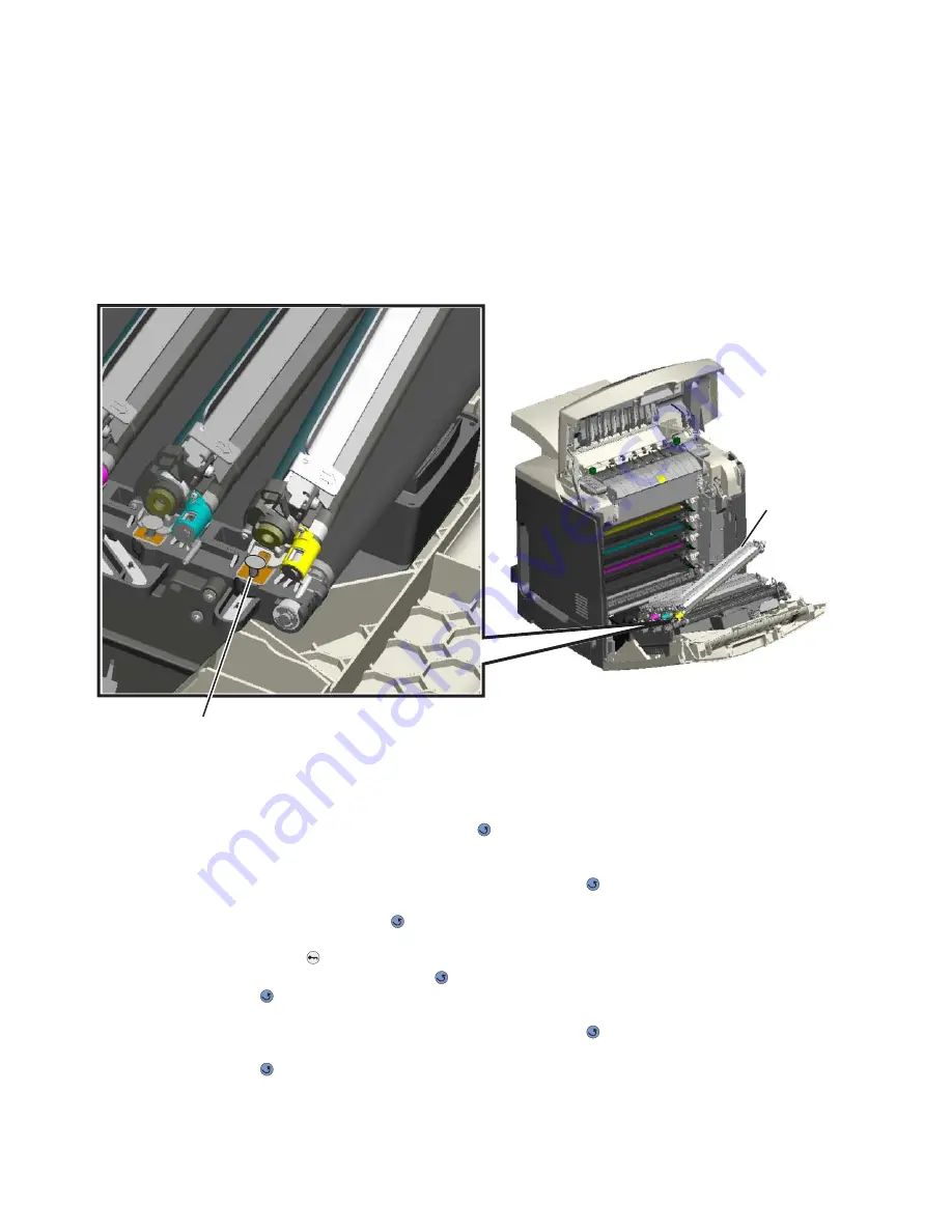
Photoconductor unit removal
Warning: To avoid damaging the photoconductor drum, hold the photoconductor units by their handle and
place the photoconductor units on a clean surface. See
“Handing the photoconductor unit” on
page 4-2
for additional information.
1.
Open the top access door.
2.
Open the front access door.
3.
Lift the right end handle (A) of the photoconductor unit, releasing from the mount.
4.
Lift the unit up and away from the left side of printer, ensuring the left end of the photoconductor is released
from the holding pin (B).
Installation note: If a new photoconductor unit is installed, reset the life count value in the printer memory.
•
If a message appears on the operator panel:
1.
When
84 <
color
> PC Unit Life Warning
or
84 Replace <
color
> PC Unit
appears,
select Supply Replaced, and then press
.
Replace Supply
displays.
2.
Select Cyan PC Unit, Magenta PC Unit, Yellow PC Unit, or Black PC Unit based on the
photoconductor unit that was just replaced, and then press
.
<
color
> PC Unit Replaced
displays.
3.
Select Yes, and then press
to clear the message.
•
If no message appears:
1.
Press Menu (
).
2.
Select Supplies Menu, and press
.
3.
Press
to
select
Replace Supply.
4.
Select Cyan PC Unit, Magenta PC Unit, Yellow PC Unit, or Black PC Unit based on the
photoconductor unit that was just replaced, and then press
.
<color> PC Unit Replaced
displays.
Press
to
select
Yes.
A
B
Summary of Contents for C52 series
Page 13: ...Laser notices xiii 5022 xxx Japanese Laser Notice ...
Page 14: ...xiv Service Manual 5022 xxx Korean Laser Notice ...
Page 125: ...Diagnostic aids 3 31 5022 xxx ...
Page 150: ...3 56 Service Manual 5022 xxx ...
Page 164: ...4 14 Service Manual 5022 xxx Cover removals ...
Page 177: ...Repair information 4 27 5022 xxx Installation note Be sure the tab B is fully engaged B ...
Page 180: ...4 30 Service Manual 5022 xxx 9 Remove the linkage screw C C ...
Page 184: ...4 34 Service Manual 5022 xxx 10 Remove the linkage screw C C ...
Page 256: ...4 106 Service Manual 5022 xxx ...
Page 257: ...Locations and connectors 5 1 5022 xxx 5 Locations and connectors Locations Covers ...
Page 260: ...5 4 Service Manual 5022 xxx Rear ...
Page 263: ...Locations and connectors 5 7 5022 xxx CRU and FRUs ...
Page 264: ...5 8 Service Manual 5022 xxx Sensors Toner level sensor Toner patch sensor TPS ...
Page 265: ...Locations and connectors 5 9 5022 xxx Motors ...
Page 266: ...5 10 Service Manual 5022 xxx Printer cards ...
Page 267: ...Locations and connectors 5 11 5022 xxx Connectors System card network models C52x ...
Page 268: ...5 12 Service Manual 5022 xxx System card non network models C52x ...
Page 274: ...5 18 Service Manual 5022 xxx System card network models C53x ...
Page 280: ...5 24 Service Manual 5022 xxx ...
Page 282: ...6 2 Service Manual 5022 xxx ...
Page 284: ...7 2 Service Manual 5022 xxx Assembly 1 Covers 15 1 2 3 4 9 5 8 10 12 13 14 6 7 11 ...
Page 286: ...7 4 Service Manual 5022 xxx Assembly 2 Front ...
Page 288: ...7 6 Service Manual 5022 xxx Assembly 3 Right ...
Page 290: ...7 8 Service Manual 5022 xxx Assembly 4 Rear ...
Page 292: ...7 10 Service Manual 5022 xxx Assembly 5 Left 1 2 3 ...
Page 294: ...7 12 Service Manual 5022 xxx Assembly 6 Top 1 2 ...
Page 296: ...7 14 Service Manual 5022 xxx Assembly 7 Customer replaceable units CRUs 3 4 1 2 5 6 2 ...
Page 298: ...7 16 Service Manual 5022 xxx Assembly 8 Contact springs ...
Page 300: ...7 18 Service Manual 5022 xxx Assembly 9 Cable parts packet ...
Page 312: ...I 10 Service Manual 5022 xxx ...
Page 313: ......
Page 314: ......


