


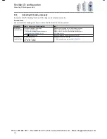


11.2
Controller enable, starting & stopping, reversal
Configuration of the triggers for the following basic functions for traversing the drive:
•
Controller enable - enable/inhibit operation.
•
Start enable - start drive / enable start functions.
•
Quick stop - bring drive to a standstill in best time.
•
Forward start (CW) / backward start (CCW) - start drive in edge-controlled fashion.
•
Forward run (CW) / backward run (CCW) - start/stop drive in status-controlled fashion.
•
Forward jog (CW) / backward jog (CCW) - traverse drive with preset setpoint.
•
Change of direction of rotation
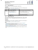
Preconditions
•
The triggers for start and stop commands set in 0x2631 (PAR 400) are only effective if selec-
tion "0" (terminal mode) is set in
0x2824 (PAR 200)
.
•
In terminal mode, either the "Controller enable" function or the "Start enable" function
must be connected to an input so that the drive can be stopped again anytime!
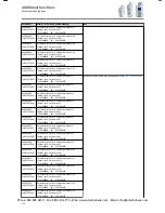
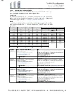
Parameter
Name / value range / [default setting]
Info
0x2631:001
(PAR 400/001)
Function assignment: Controller enable
(Function list: Controller enable)
•
Setting can only be changed if controller inhibit is
active.
Assignment of a trigger for the "Controller enable" function.
Trigger = TRUE: The inverter is enabled (unless there is another cause for
controller inhibit).
Trigger = FALSE: The inverter is inhibited. Starting the drive is not possi-
ble.
Notes:
•
In all device states, a TRUE-FALSE edge causes an immediate change
to the inhibited state with one exception: If the inverter is in the error
status and the error condition still exists, the inverter remains in the
error status.
•
Changing to the inhibited state causes an immediate stop of the drive,
regardless of the stop method set in
0x2838:003 (PAR 203/003)
. The
drive coasts down as a function of the mass inertia of the machine.
•
The causes that are active for controller inhibit are shown in
0x282A:
001 (PAR 126/001)
.
0 Not connected
No trigger assigned (trigger is constantly FALSE).
1 Constant TRUE
Trigger is constantly TRUE.
11 Digital input 1
State of X3/DI1, taking an inversion set in
0x2632:001 (PAR 411/001)
into
consideration.
12 Digital input 2
State of X3/DI2, taking an inversion set in
0x2632:002 (PAR 411/002)
into
consideration.
13 Digital input 3
State of X3/DI3, taking an inversion set in
0x2632:003 (PAR 411/003)
into
consideration.
14 Digital input 4
State of X3/DI4, taking an inversion set in
0x2632:004 (PAR 411/004)
into
consideration.
15 Digital input 5
State of X3/DI5, taking an inversion set in
0x2632:005 (PAR 411/005)
into
consideration.
16 Digital input 6
State of X3/DI6, taking an inversion set in into consideration.
17 Digital input 7
State of X3/DI7, taking an inversion set in into consideration.
50 Running
TRUE if motor is controlled (pulse width modulation on). Otherwise
FALSE.
51 Ready for operation
TRUE if operation is enabled AND no error is active. Otherwise FALSE.
53 Stop active
TRUE if inverter is not enabled OR Stop command is active and output
frequency = 0.
FALSE if inverter enabled OR quick stop active OR fault active OR output
frequency
≠
0.
54 Quick stop active
TRUE if quick stop is active. Otherwise FALSE.
•
With the setting "Quick stop ramp -> switch-on inhibited" in
0x605A
,
the "Quick stop active" status is reset to FALSE after ramp-down to
standstill.
•
With the setting "Quick stop ramp -> quick stop active" in
0x605A
, the
"quick stop active" status remains TRUE until the "quick stop" func-
tion is activated.
Flexible I/O configuration
Controller enable, starting & stopping, reversal
188
Phone: 800.894.0412 - Fax: 888.723.4773 - Web: www.actechdrives.com - Email: [email protected]