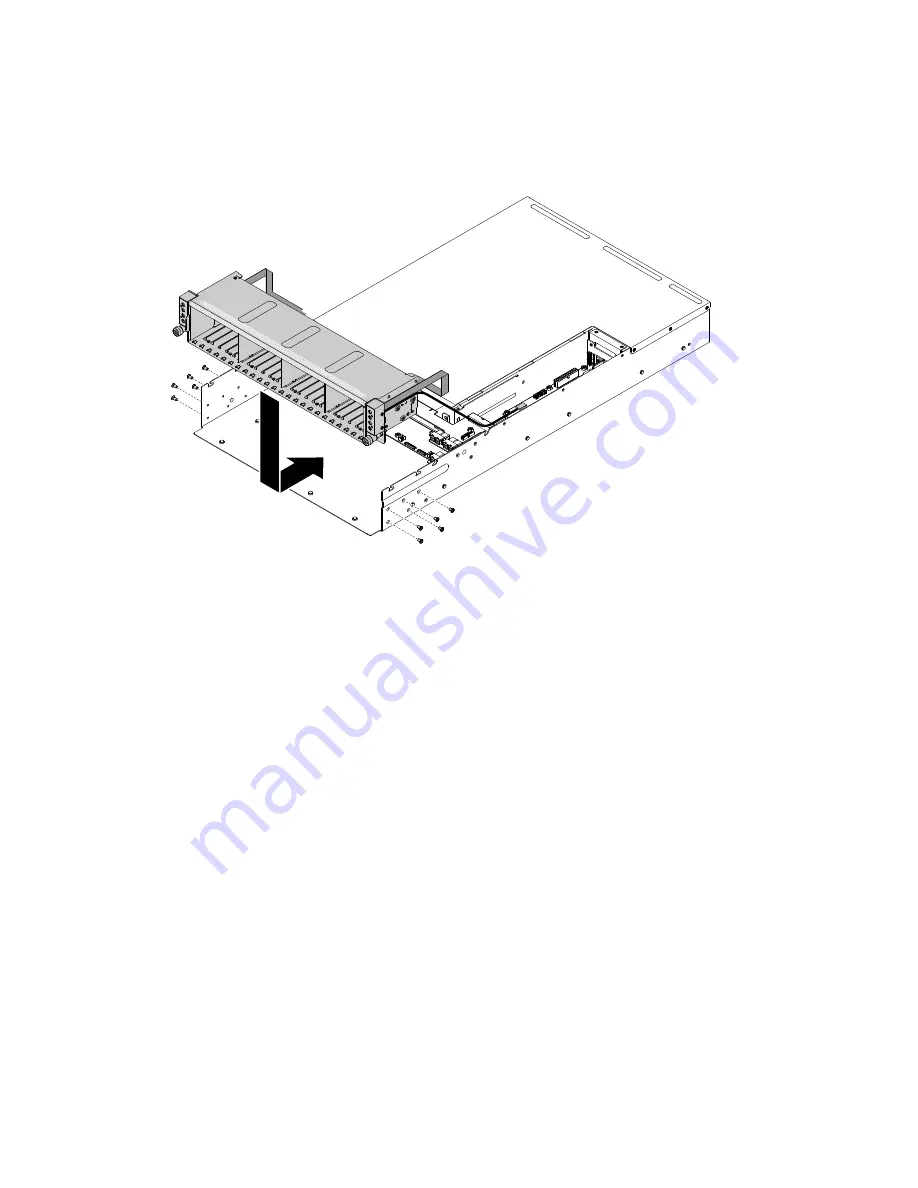
Step 3.
Align the hard disk drive cage assembly bottom with the cage pin holes on the server chassis.
Step 4.
Lower the hard disk drive cage assembly into the server. Press the hard disk drive cage assembly
inward until it is securely seated.
000
000
000
0
0
00
Figure 64. Hard disk drive cage installation
Step 5.
Tighten the hard disk drive cage with 10 M3 screws.
Step 6.
Reinstall the hard disk drive backplane and connect the cables.
Step 7.
Reinstall the cables, including hard disk drive backplane configure cable (x1), hard disk drive
backplane power cable (x2), SAS cables (x8), thermal sensor cable (x1) and front I/O cable (x2).
Step 8.
Reinstall the system fan (see “Replacing a system fan” on page 89).
Step 9.
Reinstall the system management board cover (see “Installing the system management board
cover” on page 85).
Step 10. Reinstall the fan cage cover (see “Installing the fan cage cover” on page 83).
Step 11. Reinstall the hard disk drive (see “Installing a hot-swap hard disk drive” on page 91).
1. Install the server into the rack enclosure and push the server into the rack until it clicks into place.
2. Reconnect the power cords and any cables that you removed.
3. Turn on the peripheral devices and the server.
Removing a microprocessor and heat sink
Use this information to remove a microprocessor and heat sink.
• Microprocessors are to be removed only by trained technicians.
Important:
Always use the microprocessor installation tool to remove a microprocessor. Failing to use
the microprocessor installation tool may damage the microprocessor sockets on the system board. Any
damage to the microprocessor sockets may require replacing the system board.
Removing and replacing server components
125


