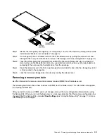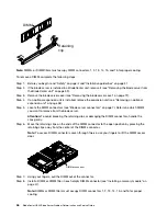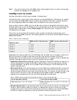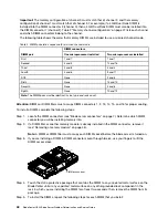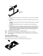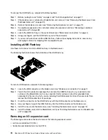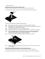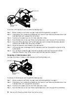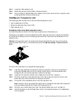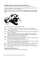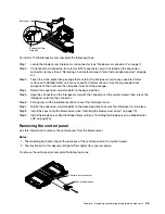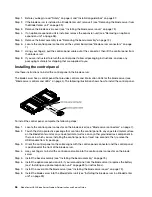
power-on LED flashes rapidly, and the power-control button on the blade server does not respond
until this process is complete.
Step 6. Turn on the blade server (see “Turning on the blade server” on page 6 for instructions).
Step 7. Make sure that the power-on LED on the blade server control panel is lit continuously, indicating
that the blade server is receiving power and is turned on.
Step 8. If you have other blade servers to install, do so now.
Step 9. Write identifying information on one of the labels that come with the blade servers and place the
label on the BladeCenter unit bezel. See the documentation for your BladeCenter unit for
information about the label placement.
Important:
Do not place the label on the blade server or in any way block the ventilation holes on
the blade server.
If you have changed the configuration of the blade server or if you are installing a different blade server from
the one that you removed, you must configure the blade server through the Setup utility, and you might have
to install the blade server operating system. Detailed information about these tasks is available in the
Installation and User's Guide
.
Removing and replacing Tier 1 customer replaceable units (CRUs)
Use this information for removing and replacing Tier 1 CRUs.
Replacement of Tier 1 CRUs is your responsibility. If IBM installs a Tier 1 CRU at your request, you will be
charged for the installation.
Some Tier 1 CRUs are available as both optional devices and replaceable components. You can use the
installation instructions for the Tier 1 CRU to install the optional device.
Removing the battery
Use this information to remove the battery from the blade server.
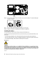
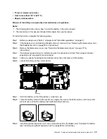
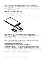
To remove the battery, complete the following steps.
Step 1. Before you begin, read “Safety” on page iii and “Installation guidelines” on page 37.
Step 2. If the blade server is installed in a BladeCenter unit, remove it (see “Removing the blade server from
the BladeCenter unit” on page 39 for instructions).
Step 3. Remove the blade server cover (see “Removing the blade server cover” on page 72 for
instructions).
Step 4. If an optional expansion unit is installed, remove the expansion unit (see “Removing an optional
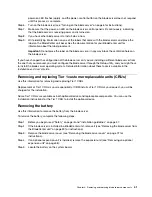
Step 5. Locate the battery on the system board.
.
Removing and replacing blade server components
41
Summary of Contents for BladeCenter HS23 1929
Page 1: ...BladeCenter HS23 Blade Server Problem Determination and Service Guide Machine Types 7875 1929 ...
Page 284: ...268 BladeCenter HS23 Blade ServerProblem Determination and Service Guide ...
Page 289: ...Taiwan BSMI RoHS declaration Appendix B Notices 273 ...
Page 290: ...274 BladeCenter HS23 Blade ServerProblem Determination and Service Guide ...
Page 296: ...280 BladeCenter HS23 Blade ServerProblem Determination and Service Guide ...
Page 297: ......
Page 298: ...Part Number 00KC215 Printed in China 1P P N 00KC215 ...
Page 299: ... 1P00KC215 ...

