


Important:
The memory configuration of channel 0 must match that of channel 2, and the memory
configuration of channel 1 must match that of channel 3. For example, if a 4 GB Dual Rank DIMM is
installed into the DIMM connector 3 (channel 0), then a 4 GB Dual Rank DIMM must also be installed into
the DIMM connector 7 (channel 2). Table 2 “Memory channel configuration” on page 47 lists each channel
and which DIMM connectors belong to the channel.
The following table shows the order that memory DIMMs are installed to use a mirrored channel mode.
Table 4. DIMM population sequence for mirrored channel mode
DIMM pair
DIMM connectors
One microprocessor installed
Two microprocessors installed
First
1 and 7
1 and 7
Second
3 and 5
14 and 16
Third
2 and 8
3 and 5
Fourth
4 and 6
9 and 11
Fifth
None
2 and 8
Sixth
None
13 and 15
Seventh
None
4 and 6
Eighth
None
10 and 12
Note:
The DIMM pairs must be identical in size, type, and rank count.
Attention:
DIMMs or DIMM fillers must occupy DIMM connectors 1, 2, 13, 14, 15, and 16 for proper cooling.
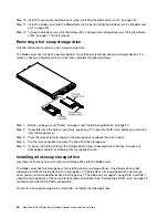
To install a DIMM, complete the following steps:
Step 1. Locate the DIMM connectors (see “Blade server connectors” on page 7). Determine which DIMM
connector you will be installing memory into.
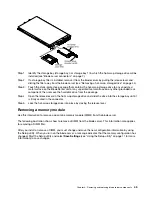
Step 2. If a DIMM filler or another memory module is already installed in the DIMM connector, remove it
(see “Removing a memory module” on page 45).
Note:
A DIMM or DIMM filler must occupy each DIMM socket before the blade server is turned on.
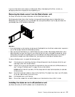
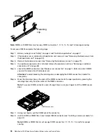
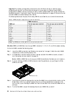
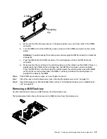
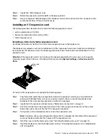
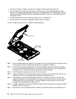
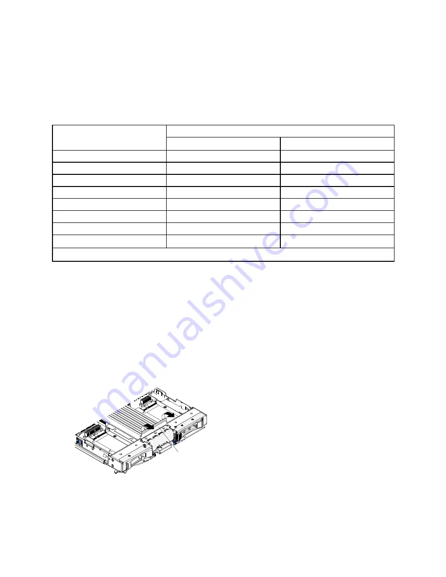
Step 3. If you are installing a DIMM in DIMM connector seven through twelve, use your fingers to lift the
DIMM access door.
DIMM access door
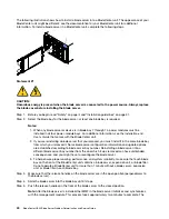
Step 4. Touch the static-protective package that contains the DIMM to any
unpainted
metal surface on the
BladeCenter unit or any
unpainted
metal surface on any other grounded rack component in the
rack in which you are installing the DIMM for at least two seconds; then, remove the DIMM from its
package.
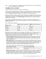
Step 5. To install the DIMMs, repeat the following steps for each DIMM that you install:
48
BladeCenter HS23 Blade ServerProblem Determination and Service Guide
Summary of Contents for BladeCenter HS23 1929
Page 1: ...BladeCenter HS23 Blade Server Problem Determination and Service Guide Machine Types 7875 1929 ...
Page 284: ...268 BladeCenter HS23 Blade ServerProblem Determination and Service Guide ...
Page 289: ...Taiwan BSMI RoHS declaration Appendix B Notices 273 ...
Page 290: ...274 BladeCenter HS23 Blade ServerProblem Determination and Service Guide ...
Page 296: ...280 BladeCenter HS23 Blade ServerProblem Determination and Service Guide ...
Page 297: ......
Page 298: ...Part Number 00KC215 Printed in China 1P P N 00KC215 ...
Page 299: ... 1P00KC215 ...