Locating components
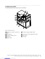
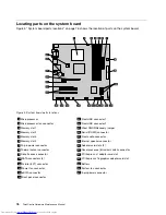
The following illustration shows the major parts in the computer.
Figure 4. Component locations
1
Microprocessor, heat sink, and heat sink fan
assembly
6
PCI Express x16 graphics adapter card slot
2
Memory slots (4)
7
Cover presence switch (also called intrusion switch)
3
PCI Express x1 adapter card slot
8
Rear system fan
4
Adapter card
9
Power supply
5
Adapter card slot
Chapter 8
.
Replacing FRUs (Machine Types: 3063, 3231, 3285, 4084, 4085, 4086, 4087, 6138, 6209, 6239, 6302, 7188, 7244,
7347, 7355, 7358, 7373, 7484, 7571, 7628, 7635, 7639, 8494, 8854, 9728, 9960, and 9965.)
75
Summary of Contents for 7220AGU - ThinkCentre M58p Desktop
Page 2: ......
Page 8: ...vi ThinkCentre Hardware Maintenance Manual ...
Page 17: ...Chapter 2 Safety information 9 ...
Page 21: ...Chapter 2 Safety information 13 ...
Page 22: ...1 2 14 ThinkCentre Hardware Maintenance Manual ...
Page 23: ...Chapter 2 Safety information 15 ...
Page 29: ...Chapter 2 Safety information 21 ...
Page 33: ...Chapter 2 Safety information 25 ...
Page 42: ...34 ThinkCentre Hardware Maintenance Manual ...
Page 50: ...42 ThinkCentre Hardware Maintenance Manual ...
Page 54: ...46 ThinkCentre Hardware Maintenance Manual ...
Page 78: ...70 ThinkCentre Hardware Maintenance Manual ...
Page 566: ...558 ThinkCentre Hardware Maintenance Manual ...
Page 570: ...562 ThinkCentre Hardware Maintenance Manual ...

