


Section 4: PFS8010 Assembly & Set-Up
PFS4000, PFS5060 & PFS8010 Pendulum Spreaders 309-124M
11/20/20
23
Hopper Assembly
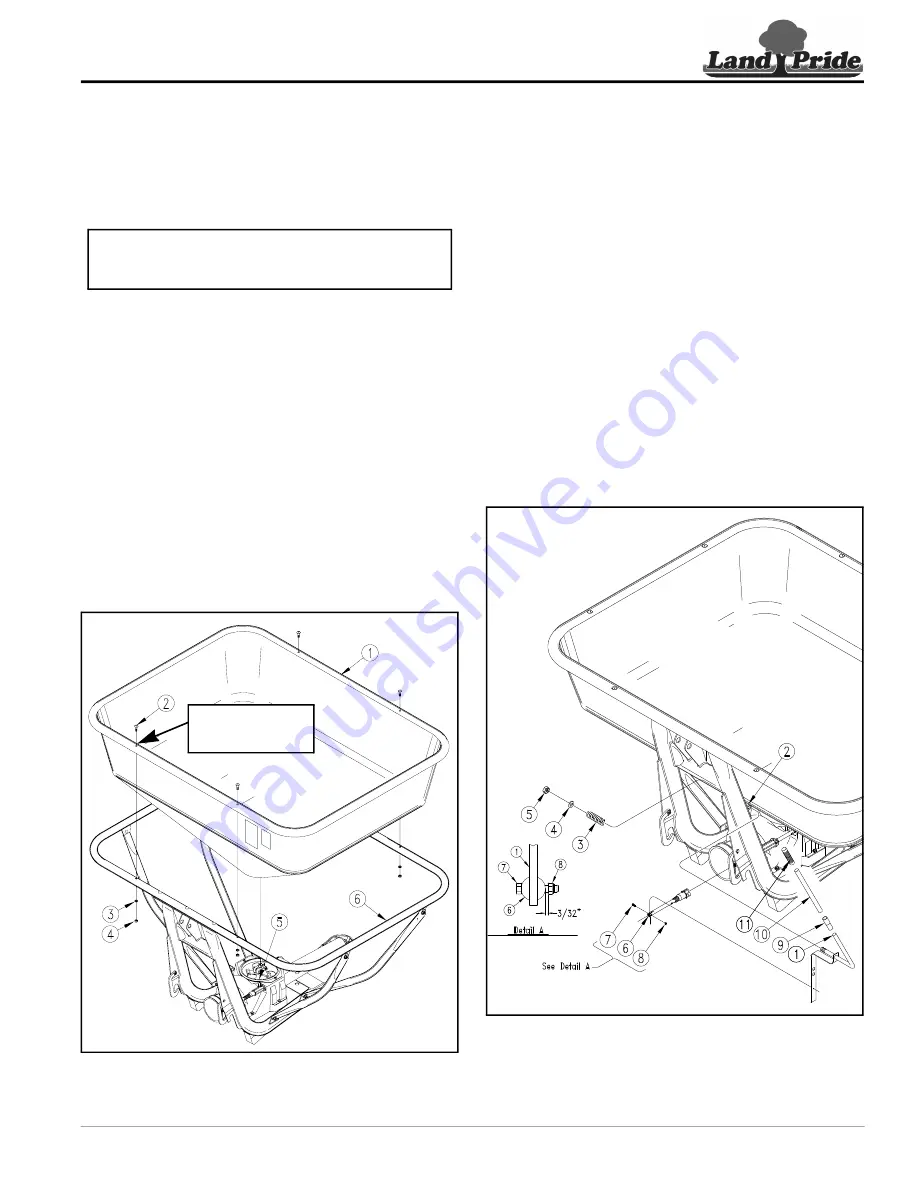
Refer to Figure 4-4:
1. Orient hopper (#1) with decals facing front as shown
and lower hopper onto hopper support ring (#6).
Make sure drive unit (#5) is centered under the
hopper bottom. (Land Pride Logo is on the back.)
2.
Refer to
forward and backward to make certain hopper is
centered and fully seated on drive unit. Tighten hex
nuts (#4 & #6) to the correct torque.
3. If included, install optional hopper extension at this
time. See “Hopper Top Extension Kit” on page 30 for
installation instructions.
4. Using holes in hopper support ring as a template,
slowly dill 10 mm (13/32") diameter holes up from the
bottom through the hopper flange.
5. Attach hopper to hopper support ring with M10 x 80
(3 1/8") round head screws (#2), flat washers (#3)
and hex head nuts (#4). Do not tighten nuts until after
all bolts and nuts have been installed.
6. Position flat face of bolt facing forward and tap heads
in before tightening nuts. Hand tighten nuts (#4) with
a hand wrench. (Do not use power wrench.)
Hopper Assembly
Figure 4-4
NOTE:
Make certain hopper is fully seated against
hopper support ring on all four sides before
continuing with step 2 below.
30772
Locate & drill holes
in hopper flange in
field assembly.
Gate Lever Assembly
Refer to Figure 4-5:
1. Insert gate lever (#1) into mounting bracket (#2) as
shown and secure with compression spring (#3), flat
washer (#4) and self locking hex nut (#5). Draw nut
up snug, do not tighten.
2. Spread fork on end of regulation bar (#6) and attach
gate lever (#1) to regulation bar (#6) with
M6 x 25 (1") hex bolt (#7) and hex nut (#8).
See Detail “A”:
Draw hex locknut (#8) up until bolt
has approximately 3/32" movement.
3. Attach handle (#11) to gate lever extension (#10).
4. Attach gate lever extension (#10) to gate lever (#1)
with PVC sleeve (#9).
5. Tighten nylock nut (#5) until lever (#1) has enough
resistance to not move during field use. Some
adjustment to nut (#5) may be required during field
application. Make sure nylock nut has full thread
engagement.
6. Turn to page 24 for “Driveline Assembly and Set-Up”
instructions.
Gate Lever Assembly
Figure 4-5
30773


