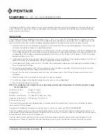
background image

21

C

A

B

A. Auger Motor

B. Auger Shaft

C. Solenoid

10.  Remove the Auger Motor Shaft Key and set aside.
11.  Remove the second clip from the Auger Shaft.
12.  Disconnect the Ice Chute wire harness from the junction box.
13.  Disconnect the solenoid from Ice Chute link by pushing pin 

through shaft until link is free. (Pin shown in out position)

C

A

B

A. Solenoid

B. Solenoid Pin

C. Ice Chute Link

14. 

Remove the Ice Chute Assembly by first removing nozzle 

plate and right side panel, then removing the four (4) screws 

that secure to unit and set aside.

15.  Remove Auger by pulling straight out from unit and set aside.

A

B

A. Auger Motor

B. Remove Screws

Cleaning & Sanitizing Syrup Lines - Bag in Box

1.  Disconnect syrup lines from BIB’s
2.  Place syrup lines, with BIB connectors and any adapters, in 

a bucket of warm water.

3. 

Activate each valve to fill the lines with warm water and flush 

out syrup remaining in the lines.

4.  Prepare Cleaning Solution described on previous page 19. 

Following sanitation, rinse with end-use product until 

there is no aftertaste. Do not use a fresh water rinse. 

This is a NSF requirement. Residual sanitizing solution 

left in the system creates a health hazard.

CAUTION

A

B

C

A. Agitator Clip/Pin

B. Hub

C. Agitator Bar

16.  Remove Agitator Clip and Pin from Agitator bar in Ice Bin.

17.  Remove the Agitator bar and Hub from the Ice Bin.

18. 

Using the Cleaning Solution (page 19) and a clean cloth or 

soft brush, clean the Ice Chute Assembly, Ice Shroud, Auger, 

all sides of the Ice Bin, and surface of the aluminum casting.

5.  Place syrup lines, with BIB connectors and any adapters, 

into cleaning solution.

6. 

Activate each valve until lines are filled with cleaning        

solution then let stand for ten (10) minutes. 

7.  Flush out cleaning solution from the syrup lines using clean, 

warm water.

8. 

Prepare Sanitizing Solution described on page 19. 

9.  Place syrup lines into sanitizing solution and activate each 

valve to fill with sanitizer. Let sit for ten (10) minutes.

10. 

Reconnect syrup lines to BIB’s and draw drinks to flush  

solution from the dispenser.

11. 

Taste the drink to verify that there is no off-taste. If off-taste 

is found, flush syrup system again.

19.  Using the Cleaning Solution and the sponge brush provided, 

clean all interior surfaces of the ice chute and the ice chute 

feed through.

20.  Using hot water, thoroughly rinse away the cleaning solution.
21.  Wearing sanitary gloves, use a clean cloth or towel and the 

Sanitizing Solution (page 19) to wash all surfaces of  

removable parts, sides of the Ice Bin, and surface of the 

aluminum casting.

22.  Using the Sanitizing Solution and the sponge brush          

provided, clean all interior surfaces of the ice chute and the 

ice chute feed through.

23.  Wearing sanitary gloves, reassemble all removable parts. 

Ensure agitator clip is locked.

24.  Fill unit with ice and replace Top Cover.
25.  Reconnect dispenser to power source.


 Après avoir désinfecté la distributrice, rincez avec le pro-

duit final jusqu’à ce qu’il ne subsiste aucun arrière-goût. 

N’utilisez pas d’eau de rinçage. Ceci est une exigence de 

la NSF. Les résidus du produit désinfectant présentent un 

risque pour la santé.

MISE EN GARDE

Summary of Contents for Twin Pour 30

Page 1: ...not be used by children or infirm persons without supervision This appliance can be used by children aged from 8 years and above and persons with reduced physical sensory or mental capabilities or la...

Page 2: ...hez pas cet appareil dans une prise lectrique multiple partag e par d autres appareils Ne placez pas plusieurs prises d alimentation multiples portables ou alimentations lectriques portables l arri re...

Page 3: ...an air gap a backflow prevention device or another approved method to comply with NSF standards A leaking inlet water check valve will allow carbonated water to flow back through the pump when it is s...

Page 4: ...aining three sides Level unit if necessary For optimum perfor mance place the unit at a 0 tilt The maximum tilt is 5 Leveling the Dispenser NSF listed units must be sealed to the counter NOTE To ensur...

Page 5: ...at se trouve dans le bac gla ons Durant le cycle d agitation automatique et lors de la distribution des gla ons veiller ce que l espace soit suffisant entre le dessus de l amas de gla ons et le bas de...

Page 6: ...nect tubing to all syrup inlets See Plumbing Diagrams on page 26 for reference NOTE 12 Route drain hose from designated open type drain to fitting on Drip Tray and connect hose to fitting if applicabl...

Page 7: ...E 13 Attach fan bracket to fan assembly using screws provided Condensation Fan Installation 14 Install condensation fan on the underside of the unit by 1 pushing fan bracket into slots in the right wa...

Page 8: ...OT TURN ON CO2 SUPPLY AT THIS TIME WARNING 7 Repeat Step 6 for both low pressure CO2 regulators on the regulator manifold routed to the unit and the syrup pumps 5 Connect tubing routed from the tee at...

Page 9: ...the service menu for drink setup must be accessed 10 Access the Service Menu by turning the keyswitch clock wise to the third position 6 Turn on the power to the dispenser by pressing the on off toggl...

Page 10: ...oth of the low pressure regulators on the regulator manifold to 75 psi 0 517 MPa then tighten locknut with wrench 22 Activate each soda module until gas out 23 Plug in the remote carbonator pump deck...

Page 11: ...button on the lower left corner to return to the Valve Configuration Screen 7 Repeat Steps 3 and 5 for any of the other brand or flavor modules 8 Tap the Back button to return to the Service menu 12 T...

Page 12: ...bration button 2 Tap the Calibrate on the Water Valve to be calibrated Calibrating Plain Carbonated Water Modules Fill to 200 ml Graduated Cylinder CALIBRATION MAINTENANCE 4 Set the Timer to the ON po...

Page 13: ...r reference The water flow rate was set to 73 93 ml sec which makes the final syrup flow rate 14 79 ml s The finished drink flow rate dispensed will be 88 72 ml s NOTE A B C D Increase Decrease A Flow...

Page 14: ...ttach outer nozzle by pushing up and twisting clockwise until snug 5 Enter the brand calibration screen from the previous section steps 1 2 6 Set the Timer to the ON position and select Time as the Op...

Page 15: ...The following is a set of instructions on how to set up this feature If no sold out sensor is assigned then the Auto feature acts the same as the Ready feature NOTE Sold Out Features 1 From the Servic...

Page 16: ...d scroll down and press Accept to confirm and save changes It may take up to 10 minutes for a network connection to be established NOTE 2 From the service menu select Network Status to change connecti...

Page 17: ...into open port on the side of the PCB controller box 4 Access the Service menu on the left side screen and tap the Data Management button Update Brands Flavors 1 Create a USB drive with the updated b...

Page 18: ...ment aux lignes directrices de la NSF L exploitant de l quipement doit en assurer l entretien continu comme indiqu dans ce manuel ou selon les lignes directrices du minist re de la Sant afin d assure...

Page 19: ...n Box on page 21 Pull out unit if applicable and clean behind and underneath Check for any loose components or noises Other Supplies Needed 1 Clean cloth towels 2 Bucket 3 Extra nozzle 4 Sanitary glov...

Page 20: ...in the sanitizing solution using the nozzle brush dip the brush in the nozzle sanitizing solution and thoroughly brush the bottom of the inner nozzle body 6 Rinse the brush in warm 90 110 F 32 2 43 3...

Page 21: ...all sides of the Ice Bin and surface of the aluminum casting 5 Place syrup lines with BIB connectors and any adapters into cleaning solution 6 Activate each valve until lines are filled with cleaning...

Page 22: ...coming CO2 pressure is between 70 psi 0 483 MPa and 80 psi 0 552 MPa 2 Open shutoff fully 3 Remove soda flow control from valve and clean out any foreign material to ensure smooth spool movement Insuf...

Page 23: ...to syrup pump too low 5 Stalled or inoperative BIB pump 6 Kinked line 7 CO2 regulator malfunction 1 Replace syrup BIB as required 2 Open shutoff completely 3 Remove valve from mounting block open shu...

Page 24: ...Wiring harness not plugged in 3 PC board defective 4 Malfunctioning power supply 1 Connect dispenser to power source 2 Plug in wiring harness 3 Replace PC board 4 Check voltage to power supply Check f...

Page 25: ...ck BIB connector if still leaking then re place line 2 Replace o ring 3 Replace defective pump BIB pump fails to restart after bag replacement 1 BIB connector not on tightly 2 BIB connector is stopped...

Page 26: ...12 14 16 2 4 6 16 8 10 12 14 1 3 5 7 9 NC 11 13 15 NC 1 3 5 15 7 9 11 13 BLK WHT GRY BLK PUR BLU GRN YEL ORG RED BRN VIO BLK BLK GRN BLK BRN BLK ORG BLK BLK BLK GRY PUR BLU GRN YEL ORG RED BRN WHT BLK...

Page 27: ...R USB DC BLOCK OK POWER CORD CONDENSATION FAN PRIMARY PCB SECONDARY PCB POUR BUTTON POUR BUTTON GPIO ICE DOOR TRIGGER VALVEHARN RIGHT VALVEHARN LEFT SBC USB A TO USB B DIO PCB POWER SUPPLY USB A MALE...

Page 28: ...SATION FAN PRIMARY PCB SECONDARY PCB GRN DC FAN AC OUT AC VOLT TO SUPPLY GRN BLU BLK DIO PCB BLK RED RED BLK BLK RED DENOTES DEFAULT 3 2 SW2 SWITCH 2 POSITION DOES NOT MATTER 4 ON LANCER PN 06 3289 01...

Page 29: ...29...

Page 30: ...A HOSHIZAKI COMPANY 6655 Lancer Boulevard San Antonio TX 78219 lancerworldwide com...

Reviews: