LAGUNA
TOOLS
27
1.
Mount
touch
probe
into
the
spindle.
1.1
Using
a
suitable
collect
(3/8")
and
clamping
nut(ER20
‐
A
‐
W).
1.2
Fasten
the
touch
probe’s
connector
into
the
connector
on
the
gantry.
1.3
Bundle
the
touch
probe's
wire
and
secure
it
into
the
clip
located
on
the
spindle
mounting
plate.
Leave
extra
slack
between
the
clip
and
connector
to
allow
for
travel
along
the
Z
‐
axis.
2.
Verify
that
the
touch
probe
is
working
properly
before
proceeding
to
prevent
damage
to
the
probe.
2.1
Manually
activate
the
touch
probe
and
verify
that
the
touch
probe
indicator
in
your
winCNC
controller
changes
state
from
Red
to
Green,
as
seen
to
the
right
2.2
If
touch
probe
indicator
does
not
change
state,
do
not
proceed
until
fault
is
corrected.
3.
Fasten
the
part
to
be
scanned
to
the
spoil
board.
3.1
This
can
be
done
by
using
double
‐
sided
tape
or
vacuum
if
your
machine
is
equipped
with
a
vacuum
table.
3.2
For
demonstration
purposes,
the
sample
part
seen
to
the
right
will
be
used
throughout
this
walkthrough.
4.
Enter
the
L82Z0
command
in
the
command
window
4.1
Position
the
touch
probe
such
that
it
can
travel
in
the
negative
Z
‐
direction
and
touch
off
on
what
will
be
the
Z
‐
Zero
plane.
Normally
this
is
the
material
the
object
is
mounted
to.
4.2
The
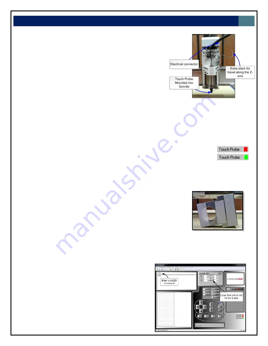
L82Z0
command
measures
the
surface
with
the
probe
and
sets
the
measured
point
to
be
the
Z0
‐
plane.
Note:
This
step
is
not
required
to
execute
a
3D
‐
scan
but
it
will
correctly
establish
the
Z
Zero
Plane
for
rendering
in
CAD
software.
Otherwise
the
Z
Zero
plane
will
need
to
be
adjusted
in
CAD
software.
Figure
34.
Touch
probe
mounting
Figure
35.
Fastening
a
part
using
double
sided
tape
Figure
36.
(Right)
Controller
screen
shot
after
execution
of
a
L82Z0
command
Summary of Contents for CNC Swift Series
Page 54: ...LAGUNA TOOLS 54 SPECIFICATIONS...


