background image

LAGUNA


TOOLS


22


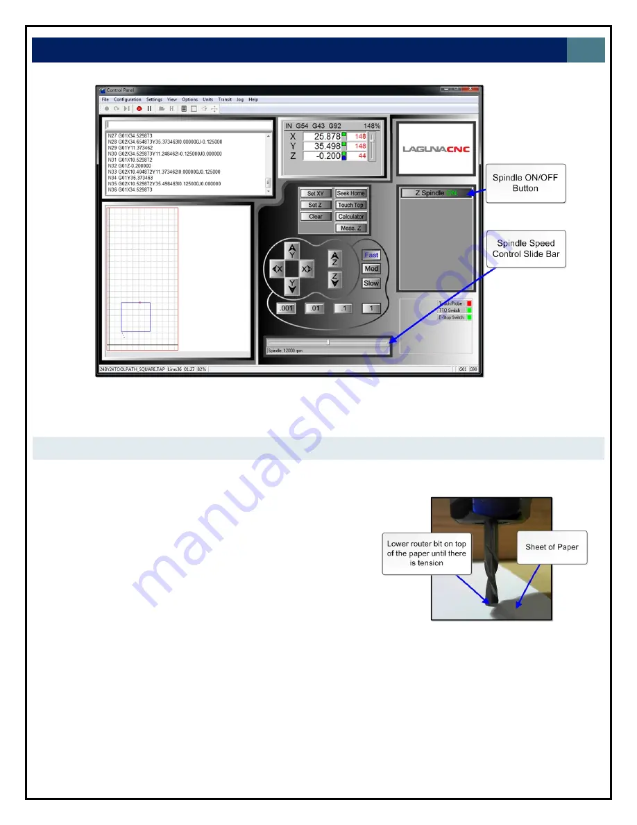
Figure


21.


Controller


interface


spindle


controls


MEASURING


TOOL


LENGTH


(TOUCH


TOP


BUTTON)


Measuring


tool


length


is


a


necessary


step


prior


to


cutting.


It


establishes


the


correct


Z


zero


plane


in


the


work


space


coordinate


system.


1.


Manual


Method


1.1


Mount


the


tool


in


the


spindle


1.2


Bring


the


tool


over


the


material


that


will


serve


as


the


Z0


plane


for


the


application.


1.3


Using


the


slow


transit


speed


setting,


lower


the


spindle


down


close


to


the


table.


1.4


Slide


a


sheet


of


paper


under


the


tool.


1.5


Lower


the


tool


down


using


the


0.001


or


0.01


incremental


transit


setting


until


there


is


tension


on


the


paper


but


enough


clearance


to


slide


the


sheet


of


paper


out.


1.6


Press


the


“SetZ”


button


in


the


control


interface.


1.6.1


A


green


box


will


appear


next


to


the


Z


coordinate


in


the


access


window.


Figure


22.


Paper


test


for


measuring


tool


length


manually

Summary of Contents for CNC Swift Series

Page 1: ...on Parkway Irvine California 92606 Ph 800 234 1976 www lagunatools com MCNC Swift 48 X 96 0233 MCNC Swift 48 X 48 1000 0233 2017 Laguna Tools Inc LAGUNA and the LAGUNA Logo are the registered trademar...

Page 2: ...empted by others Laguna Tools Inc is not responsible for additional tools or modifications sold or performed other than from by Laguna Tools Inc on any Laguna Tools Inc machine Warranty maybe voided u...

Page 3: ...s 8 Assembly and Setup 8 Where to locate your Machine 8 Unpacking the Machine 8 Setting up the Electrical Cabinet 9 Connecting Power 9 Fitting the Dust Hose 10 Spindle Cooling System 10 Control Panel...

Page 4: ...23 From Aspire to Cutting Tutorial 24 3D Scanning Guide 26 Edge Outline Scanning Guide 29 Maintenance Recommendations 32 Trouble Shooting 33 Machine will not start 33 Machine will not stop 33 Motor tr...

Page 5: ...u have contacted your supplying distributor Read carefully before operating the machine Keep the working area clean and be sure adequate lighting is available Do not wear loose clothing gloves bracele...

Page 6: ...elivered by a third party Before you unpack your new machine you will need to rst inspect the packing invoice and shipping documents supplied by the driver Insure that there is no visible damage to th...

Page 7: ...rkers PARTS OF THE CNC MACHINE 1 Bed The bed of the machine consists of a heavy steel frame and a T Slot Table The T slots are used to clamp the job or fixtures to the bed 2 Gantry The gantry straddle...

Page 8: ...ld select a solid flat floor preferably made of concrete or something similar Close to power source and dust collection UNPACKING THE MACHINE 1 To unpack your machine you will need tin snips a knife a...

Page 9: ...e to mount the monitor includes an M8 bolt wing nut and washer See figure 6 4 Place the PC on the lower shelf on the backside of the machine See figure 4 4 1 Have the front of the PC face the machine...

Page 10: ...too low the brushes may drag on the job being cut and could be cut by the router bit If it is too high and is not in contact with the job suction may not be optimal Once adjusted clamp with the clampi...

Page 11: ...is high the tank size will have to be larger If your shop is likely to be subject to freezing temperatures antifreeze must be added to the cooling water 7 Lower the water pump into the container ensu...

Page 12: ...on but the machine is not powered ON 2 2 OFF Machines primary switch is in the off position 3 Emergency Stop Switch 3 1 ON Machine will cease executing commands If the spindle is ON the spindle will p...

Page 13: ...SCRIPTION This section briefly explains all the features of the controller interface SCREEN DISPLAY OVERVIEW MENU BAR The menu bar contains many of the main features of the WinCNC software It is broke...

Page 14: ...Skeletal Digitizing L810 This scanning method scans a center line or spine and horizontal lines or ribs of the object 1 8 4 Digitize Outline Creates an outline trace around an object 1 8 5 Digitize L...

Page 15: ...iew feature 5 7 Single Step CTRL P Enable Disable single line execution of G Code files 6 Units Menu 6 1 Inches Sets the unit of measure to inches 6 2 Centimeters Sets the unit of measure to centimete...

Page 16: ...ts a command or job that is running 5 Pause Continue Motion Pauses Continues a command or job that is running 6 Open File Opens a browse box that is used to open a job file 7 View History Opens the co...

Page 17: ...displayed to the right of the position box indicates a temporary workspace G92 setting and a blue box indicates a tool length measure or workspace setting To the far right side of the axis window is...

Page 18: ...rement Buttons 3 1 These buttons allow you to specify the increment of a jog move The default unit of measure is inches INPUT INDICATORS 1 Touch Probe Indicates if touch probe has been triggered 2 TTO...

Page 19: ...the Main power switch to the OFF position 3 Close the desktop WinCNC application 4 Shut down the PC EMERGENCY STOP OPTIONS 1 Emergency Stop Button There is a emergency stop switch located on the elect...

Page 20: ...nut until it snaps into place as shown in the figure on the right 3 Note The router bit must not be fitted into the collet until the collet has been fitted into the spindle nut With the router bit fit...

Page 21: ...sing the command line 2 1 M3 Turns the spindle on Entering M3 in the command line will power the spindle but it may not begin rotating unless an RPM is set 2 2 Adjust spindle RPM manually by entering...

Page 22: ...that will serve as the Z0 plane for the application 1 3 Using the slow transit speed setting lower the spindle down close to the table 1 4 Slide a sheet of paper under the tool 1 5 Lower the tool down...

Page 23: ...ol screen press the Touch Top button 2 4 1 The spindle will automatically lower down until it makes contact with the tool touch off pad After making contact the spindle will retract to the Z home posi...

Page 24: ...ad to the controller and begin cutting It is assumed the user is familiar with their preferred CAD software so the design process in CAD software is omitted For this tutorial a simple design will be c...

Page 25: ...a maximum depth that the tool will not exceed This will prevent the tool from going below a set depth and prevent any damage to the machine and tools 7 1 Place tool touch off pad on top of spoil board...

Page 26: ...start button to begin executing 11 1 Emergency stop options include the emergency stop switch the esc button on the keyboard or the spacebar 3D SCANNING GUIDE The WinCNC controller supports 3D digitiz...

Page 27: ...to be scanned to the spoil board 3 1 This can be done by using double sided tape or vacuum if your machine is equipped with a vacuum table 3 2 For demonstration purposes the sample part seen to the r...

Page 28: ...Automatic 8 There are multiple settings that must be chosen before proceeding 8 1 Probe Type The touch supplied will be be the Up Down Side option 8 2 Axis Choose the axis for width length and retract...

Page 29: ...the Automatic Digitize dialog box is pressed Note Pressing the esc button key on your keyboard will abort any machine operation Pressing the spacebar will pause program execution and pressing enter wi...

Page 30: ...tarting location Note Depending on the starting location the X and Y scan directions will be affected These settings can be adjusted in the outline scan dialog box 5 Open the outline scan dialog box 6...

Page 31: ...program will abort This is a safety mechanism to prevent damage to the probe 6 7 3 It is recommended that a short distance be used relative to the starting position of the probe 6 7 4 If the probe is...

Page 32: ...Daily Checks Clean the machine and lubricate unpainted surfaces with a Teflon lubricant Wipe off any excess and buff with a dry polishing cloth This will reduce the likelihood of rust forming Check c...

Page 33: ...is fully out 3 Check that the electrical power cord is plugged into the power outlet 4 Check that the electrical supply is on reset the breaker 6 With the power disconnected from the machine check the...

Page 34: ...tor overheats wait until it has cooled and restart If the motor shuts down consistently check for the reason Typical reasons are dull cutting tools no water in the coolant tank blockage in the coolant...

Page 35: ...Shortcut Help F1 Tool Bar Shortcuts ESC Aborts the current file or command SPACE Pauses a file or command ENTER Starts restarts a file or command TAB Opens the command history box CTRL R Opens the res...

Page 36: ...arc L is used to allow setting laser power in vector cutting 1 100 R is the radius if R is used IJK cannot be used G3 Counter Clockwise Arc G3 L X Y I J Z W K R Moves to the position specified at Fee...

Page 37: ...cutter compensation G41 Cutter Compensation Left G41 O Compensates for differences in nominal and actual tool diameters Starts to the left on the first move O is the compensation amount on machines w...

Page 38: ...out this cycle some materials can produce a long stringer which can become a safety issue to the operator G80 End Drill Cycle Used to disable the G81 Drill Cycle mode Note Switching to G0 or G1 will a...

Page 39: ...lute coordinates G92 1 X0 leaves YZW local coordinates but sets X back to absolute coordinates G92 2 Shift LZ Coordinates G92 2 X Y Z W Similar to G92 1 except that the coordinate system shift is adde...

Page 40: ...ge L7 P Sets the acceleration to a percentage of the current acceleration P is the percentage 1 100 to set L7 alone restores the original L8 Turns Backlash Compensation On Restore INI values for all a...

Page 41: ...L13 Set Axis Mapping L13 XYZW Allows re mapping of axis on a pulse basis This means when the controlling axis takes a step the slave will follow in that direction Specify L13 alone to return to normal...

Page 42: ...fe When amount of change in the angle of the knife exceeds A the knife will lift to make the turn A is also used for angle correction in Target Mode see Knifemode Z is the position to lift to P is the...

Page 43: ...thout aborting L48 Laser Height Control Sets the target voltage to the current input voltage L51 Set D A L51 V P S Sets the output voltage for DA The V parameter is used to set the DA by voltage the P...

Page 44: ...L90 One Time Absolute L90 is used in a command to specify G90 coordinates on one line without changing program mode to G90 L91 One Time Relative L91 is used in a command to specify G91 coordinates on...

Page 45: ...vate signals L205 C deactivates signals and enables the specified channel L205 deactivates all signals and enables L210 Select Alternate Low Limits L210 XYZW Selects axis to use alternate low limits L...

Page 46: ...laser power 1 100 D sets the distance for the distance based vector laser firing L sets the distance for the off signal when perforating L251 1 Laser Dwell L251 1 D D time in seconds for dwell L252 B...

Page 47: ...l O specifies the height offset for the tool H specifies the tool height M specifies the maximum current allowed for the tool This command sets up a tool library instead of using the dialog boxes L501...

Page 48: ...ection L810 FILENAME EXT X Y I K Digitizes a slice line either in X direction or Y direction and saves the points to a text file If a drop off is encountered or distance stated in X or Y is reached th...

Page 49: ...e as M12 except the output is turned off without pausing motion M17 Pause Until Input On M17 C Wait for channel specified by to come on Port and bit addresses are set up in WINCNC INI M17 1 Run Next i...

Page 50: ...achine Adding M29 to a G0 or G1 command disables the program abort and instead stops the current G Code line but continues on the following line M29 must be specified on each line separately M37 Measu...

Page 51: ...t useful for macros that call subprograms M99 End Subprogram Ends a subprogram M99 1 Abort Initiates a commanded program abort MESSAGES AND ERROR CODES Error codes will be displayed in the message dis...

Page 52: ...entered Errors Reading CNCSCRN INI The CNCSCRN INI file contains errors or is not found Errors Reading WINCNC INI The WINCNC INI file contains errors or is not found Escape Button Pushed While Running...

Page 53: ...bprogram Nesting Too Deep Too many nested subprogram calls Tangential Knife Not Enabled The tangential knife feature is not enabled Tool Changer Not Enabled Tool changer is not set up in the WINCNC IN...

Page 54: ...LAGUNA TOOLS 54 SPECIFICATIONS...

Page 55: ...ations subject to change Machines may be shown with optional accessories 2017 Laguna Tools Inc LAGUNA and the LAGUNA Logo are the registered trademarks of Laguna Tools Inc All rights reserved 2072 Alt...

Reviews: