background image


How to Perform a Study 

NXT Go Owner’s Manual, LBL-00145, MAN2030 

32 

3.2 FreeFlow Study 

A FreeFlow study provides a measurement of the rate at which urine flows out of the body. 
It can be performed using the Urocap NXT and Synergy software provided as part of the 
LABORIE NXT system. 

 NOTE

: Before beginning the FreeFlow Study ensure that you have completed the tasks 

outlined in the 

Gathering Supplies and Equipment 

section on Page 

19

. 


Starting the FreeFlow Study 

Start the FreeFlow study as described in the 

Starting a Study

 section on page 

30

. 

The FreeFlow study requires the use of the Urocap NXT and Bluetooth Dongle NXT.  Ensure 
that the Urocap NXT device is ready to use (i.e. fully charged with the beaker in place). For 
information on preparing the Urocap NXT, refer to the 


 Preparing the Urocap

 NXT section on page 

21

. 


Performing a FreeFlow Study 

3.2.2.1 

Preview Phase 


The 

Preview

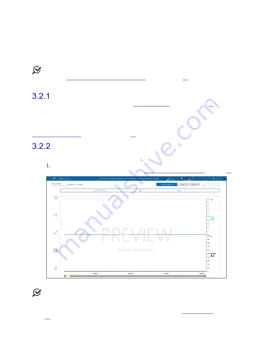
 phase begins as represented in Figure 19. For information about the 

icons in the Preview phase, refer to the 

Procedure – Preview Phase

 on page 

62

. 


Figure 19: FreeFlow Preview Phase 

 NOTE: 

Questionnaires are available through the questionnaire drop down menu and 

may be completed at any time during or after the study.  Scroll through the menu and 
select the preferred study.  A questionnaire window will appear alongside the study window.  
Press 

OK

 or 

Close 

to exit the questionnaire window.  Refer to the 

Questionnaire 

section on 

page 

65

 for an overview of the questionnaires available.  

Status DRAFT Effective

Summary of Contents for NXT Go

Page 1: ...LBL 00145 A Document No NXT Go Owner s Manual MAN2030 Title DAVID BAK David Bak Owner DRAFT Status Effective Date Expiration Date Document Build No Access Activity Accessed By Accessed Date Revision...

Page 2: ...NXT Go Owner s Manual LBL 00145 A MAN2030 NXT Go Owner s Manual Version A Status DRAFT Effective...

Page 3: ...ges renderings of LABORIE devices in this publication are property of LABORIE and may not be reproduced without the prior written permission of LABORIE Copyright 2019 2020 LABORIE Document Number LBL...

Page 4: ...ub 22 2 5 Preparing the Roam NXT 22 2 6 Preparing the UPP Puller NXT Optional 22 Assembling the UPP Puller NXT 22 Assembling the UPP Puller NXT Stand 23 2 7 Setting Up Consumables and Preparing the Pa...

Page 5: ...ming the Cystometry Study 38 3 4 2 1 Preview phase 38 3 4 2 2 Cystometry phase 38 3 4 2 3 Review and Report Phases 39 3 5 Tests 39 Stress Test 39 Urethral Pressure Profile 40 3 5 2 1 Manual Urethral P...

Page 6: ...tient Data 53 4 3 3 3 Restore or Permanently Delete Patient Data 54 4 4 Study Management 55 Workflows 55 Customizing Workflows 56 4 4 2 1 Workflow Step Settings Tabs 57 4 4 2 2 Customizing Control Pan...

Page 7: ...ing 77 5 1 3 1 Cleaning the Urocap NXT 77 5 1 3 2 Cleaning the Roam NXT and PIM NXT 78 5 1 3 3 Cleaning the NXT Go Pump Hub and the NXT Go Infusion Hook 79 5 1 3 4 Cleaning the UPP Puller NXT 79 5 1 3...

Page 8: ...Charger Isolation Diagram 90 UPP Puller NXT and Wall Charger Isolation Diagram 90 5 5 Computer Virus Protection 90 5 6 Disposing of Product After Use 91 5 7 Environmental Consideration of Waste Dispo...

Page 9: ...EMC 117 Transmitter and Wireless Compliance Statements 121 List of Figures Figure 1 NXT Go 12 Figure 2 Urocap NXT Setup 21 Figure 3 UPP Nose Locking Mechanism 22 Figure 4 Connect the UPP Motor and No...

Page 10: ...Patients 54 Figure 43 Workflow Configuration Window Channels Tab 56 Figure 44 Adding a Phase to a Custom Workflow 57 Figure 45 Workflow Configuration Window Control Panel 59 Figure 46 Action Window Ad...

Page 11: ...86 Removing the Roam NXT and PIM NXT Clips 103 Figure 87 Urocap NXT 105 Figure 88 Urocap NXT Controls 105 Figure 89 UPP Puller NXT Key Parts and Controls 107 Figure 90 T DOC NXT Air Charged Catheter...

Page 12: ...Go Owner s Manual LBL 00145 MAN2030 xi Table 19 Guidance and Manufacturer s Declaration Electromagnetic Immunity 120 Table 20 Separation Distances between Portable and Mobile RF 121 Status DRAFT Effec...

Page 13: ...he NXT family are medical device systems used for Urodynamics and pelvic floor assessment These systems can display record and store data such as vesical urethral and abdominal pressures urine flow an...

Page 14: ...and display and store data Bluetooth Dongle NXT Allows wireless communication between modules and the system Remote Control NXT Wireless and battery powered device which allows control of the system f...

Page 15: ...updates are always enabled LABORIE strongly recommends that BitLocker remain enabled on the NXT system to comply with the HIPAA standard regarding data privacy and security Ensure that an antivirus pr...

Page 16: ...feature UPP Puller NXT Add on Equipment Table 1 NXT System Configuration Standard Equipment 1 7 Warnings and Precautions Precautions Prior to Urodynamic testing a urinalysis and urine culture should b...

Page 17: ...ected to protective earth Preserve the patient connection electrical isolation Do not place the printer in the patient environment Do not reuse single use accessories After use dispose of single use a...

Page 18: ...n cords to the NXT GO System or any of its components Always position the NXT System to facilitate ease of access to all electrical connections and plugs The device operator must be able to disconnect...

Page 19: ...the PIM NXT to the Roam NXT For instructions on how to connect these devices refer to the Replacing the PIM NXT section on page 102 Connect the Roam NXT and the Urocap NXT to the PC using the NXT Mag...

Page 20: ...the user should ensure that the following supplies and equipment have been gathered and prepared for use during the procedure IMPORTANT Place the required supplies on a table or tray for easy access...

Page 21: ...rs DLC 6D RFID DLC 7D RFID CDLC 6D RFID CDLC 7D RFID 9021P5892 RFID Abdominal Pressure Fluid NXT Catheters 9021P4592 RFID 9021P4522 RFID Pressure Measurment Tubing TUB101 Disposable Cartridge and Luer...

Page 22: ...GO Carrying Case PKG1091 2 3 Preparing the Urocap NXT To prepare the Urocap NXT for use Ensure that the Urocap NXT is charged and ready to use Place the funnel on the plastic frame of the commode cha...

Page 23: ...Puller NXT Optional Ensure the UPP Puller NXT is charged LABORIE recommends charging the device overnight to ensure optimal battery power for a full day of procedures Refer to the UPP Puller NXT sect...

Page 24: ...n the thumbscrew to complete mounting To adjust any of the joints on the UPP Puller Arm loosen the thumbscrews adjust and retighten Refer to Figure 7 IMPORTANT Loosen the thumbscrews only as much as i...

Page 25: ...with a single patient only they must be replaced after every use To maintain patient safety during normal use the maximum pump speed is preset to 150ml min Always refer to the Instructions for Use pro...

Page 26: ...er to the Replacing the PIM NXT section on page 102 Position the patient in a supine or lithotomy position Open the catheter pouch and coat the distal end of the device with a water based lubricant be...

Page 27: ...RTANT T DOC Air Charged Catheters are intended for single use Synergy will not recognize a catheter that has previously been registered in the software after the allotted two hours to complete Urodyna...

Page 28: ...ir packages Remove protective covers from the back and from the connector ends of the cartridges Slide a cartridge over each transducer until it clicks in place Figure 12 Aseptically remove pressure m...

Page 29: ...it to the side luer of the stopcock Hold the catheter so that the balloon is pointing upward a For the dual lumen catheter infuse solution from the filled syringe into the catheter to force the air i...

Page 30: ...y and pressure transmission Placing the EMG Patch Electrodes Enter consumables information into the Consumable Traceability section in the Preview phase Place two electrodes peri anally at the 10 o cl...

Page 31: ...Ensure that all devices required for the study are ready i e fully charged Refer to the Hardware section on page 96 for instructions on charging the NXT System modules Verify that all devices required...

Page 32: ...as been added select the patient and proceed to the next step NOTE The following fields are mandatory for completing new patient setup First Last and Birth Date To begin the study ensure a patient is...

Page 33: ...Urocap NXT device is ready to use i e fully charged with the beaker in place For information on preparing the Urocap NXT refer to the Preparing the Urocap NXT section on page 21 Performing a FreeFlow...

Page 34: ...resume Figure 20 FreeFlow Record Phase The flow phase will stop 60 seconds after voiding ends A Post Voided Residual window Figure 21 will pop up Select the preferred method of capturing Post Voided...

Page 35: ...e user can apply the default configuration for the report or customize the report For information on customizing the report refer to the Reports section on page 65 Figure 22 FreeFlow Preview Report Cl...

Page 36: ...use of the Urocap NXT Roam NXT NXT Go Pump Hub and Bluetooth Dongle NXT Ensure all modules are connected in the Synergy Software Ensure that the Urocap NXT and Roam NXT are fully charged The Synergy...

Page 37: ...A popup window will appear and the study will pause If desired update the Fluid Density setting using the dropdown menu available on the popup window and click OK to resume the study Fluid density op...

Page 38: ...ding Phase The voiding phase will stop 60 seconds after voiding ends A Post Voided Residual window Figure 21 will pop up Select the preferred method of capturing Post Voided Residual PVR meaning the a...

Page 39: ...he bladder Click Smart Pump Up or Smart Pump Down buttons to increase or decrease the pump speed respectively NOTE To change the infusion bag click the Change Infusion Fluid button A popup window will...

Page 40: ...ovide a Filling or Cystometry phase Stress Test Commence the stress test once the patient s bladder had been infused with 150 200ml of fluid Position the patient so that the meatus the urinary opening...

Page 41: ...oggle button Once the required number of profiles is complete finish the selected study 3 5 2 2 Mechanical Urethral Pressure Profile For a Mechanical Urethral Pressure Profile ensure that the UPP pull...

Page 42: ...eused Refer to the Maintenance and Service section on page 75 for further information Remove and dispose of the Infusion Pump Tubing and any other consumables used during the study 3 7 Printing the St...

Page 43: ...ce 4 1 User Access Control Login To login to Synergy follow the steps below Double click the Synergy shortcut icon on the desktop or launch the Synergy application from the LABORIE Dashboard The Syner...

Page 44: ...ccounts are intended to link to the Active Directory of the user institution if creating domain accounts ensure that all roles within Synergy align with the Active Directory User Group roles of the us...

Page 45: ...ount select the existing account from the user list Under the Update User Info tab enter the new password and press OK Figure 29 Figure 29 Password Reset NOTE Local and Domain Users may reset their ow...

Page 46: ...below for managing user roles Click the Admin icon located on the Synergy title bar and select Mange User Role Figure 30 Figure 30 Accessing the Manage User Role Application The Manage User Role wind...

Page 47: ...ted on the Synergy title bar and select User Setup Update User Info Tab Select the newly created role press Save 4 2 Sections and Icons in the Main Window This section overviews the various features a...

Page 48: ...ble 2 Synergy Main Window Section Overview Overview of Icons in the Title Bar A brief description of the icons located on the Title Bar in the Main Window is provided in Table 3 below Refer to Figure...

Page 49: ...ow Options Description User Setup Displays the User Setup window you can add new users for Local accounts and update user information for Local users Manage User Role Displays the Manage User Role win...

Page 50: ...entered Figure 35 Default Patient Details NOTE Fields in the Patient Details section can be customized through the Patient Settings window Click the Settings Icon Patient Settings Patient Display Sett...

Page 51: ...ow will be generated Figure 36 Figure 36 Export Document Window Select the required format file path and other required options Click the OK button 4 3 1 5 Reassigning Study The reassign function allo...

Page 52: ...column Figure 37 Figure 37 Patient List EMR By default this EMR column is not visible To make it visible navigate to Settings Patient Display Settings By default the EMR field will be off Select Tabl...

Page 53: ...he Symptoms tab Figure 39 and can include Involuntary Leakage on Effort Exertion Involuntary Leakage associated with urgency and also effort exertion Post Prostatectomy Leakage Urgency with Involuntar...

Page 54: ...different location click the Browse button Click OK to save changes or click Cancel to exit By default each time patients are archived a new folder will be created in the selected location Click the A...

Page 55: ...eleted Patients Select the patients for data restore using the check boxes provided To select patients individually select individual check boxes To select all patients select the checkbox located on...

Page 56: ...Filling Voiding UPP Urogynegology 3P Urodynamics o Five phase procedure for Urodynamics using a single pressure bladder catheter o Preview Voiding Preview 2 Filling Voiding Cystometry o Two phase proc...

Page 57: ...ck OK or continue customization Configure custom workflows by completing the following steps Customize workflow step naming by selecting a step under Workflow Steps and assigning a new name under Step...

Page 58: ...able in the filling voiding and UPP phases If updating Fluid Density settings ensure to update in all relevant phases Fluid density can be changed during a study using the Change Infusion Fluid button...

Page 59: ...caling The following setting tab is available under the Review Workflow Step Settings Automatically Execute Review Control Panel 4 4 2 2 Customizing Control Panel The control panel is a customizable s...

Page 60: ...ed number of Control Panel buttons are provided Use the Row Count and Column Count fields to increase or decrease the number of buttons shown in the control panel To add or change a button s label cli...

Page 61: ...3 Accessing Hardware Channels To access hardware channels click the Settings icon in the title bar and then click Workflow Editor Select the required workflow then navigate to the Channels tab If har...

Page 62: ...rt study button when the device battery is below 15 connect the device to the applicable charging hub Connect the Urocap NXT to power using the NXT Magnetic Pogo Pin Cable Urodynamic studies cannot be...

Page 63: ...and quality process information throughout the study using quick access icons Table 7 below provides an overview of each icon s functionality Slide Sidebar Icon Button Description Patients Displays t...

Page 64: ...n alert for consumable scanning status Operators must verify that consumables have successfully scanned into consumable traceability by verifying their addition in the Consumable Traceability window F...

Page 65: ...patients Synergy allots catheters and infusion pump tubing two hours of activity once registered Synergy considers consumables as registered to a specific patient once the user proceeds to the record...

Page 66: ...click the Pause button to pause the study and click the Resume button to resume the study Questionnaire The Questionnaire workflow step provides optional questionnaires to aid in better understanding...

Page 67: ...disable various data fields by clicking the checkbox next to the required data field in the Configuration Settings The position of some data fields in the report may be moved using the Up and Down but...

Page 68: ...to the report 4 5 4 3 Quick Results and Nomograms Quick Results and Nomograms generated by Synergy are intended for use as quick references complementary to the complete study data Study results are c...

Page 69: ...on or from the Reports Workflow Step and click the Send to EMR button on the report ribbon bar This icon will only be visible if the user has an EMR license enabled When the Send to EMR button is clic...

Page 70: ...ew FreeFlow Study While in the Review window the user can Access edit and review content in the Slide Side Bar Review UDS Intelligence Score and Quick Results Edit patient details and patient history...

Page 71: ...where each phase of the test started and ended Follow the instructions below a Press the Ctrl Shift keys together This will cause the Review window to grey out b Move the vertical red marker to the ph...

Page 72: ...e NXT system for the recording phases of the study The user can expand each module to show actions required for submodules by using the plus minus boxes The color of the module indicates its status If...

Page 73: ...fair score Figure 61 Protocol Guidance Total Score and Phase Score Refer to QC Score and QC Score Summary on page 73 for an overview of how QC score is calculated 4 6 1 3 UDS Intelligence in the Revi...

Page 74: ...he report Create a new report copy or select a previously created report copy from the configuration dropdown menu NOTE Refer to the Reports section on page 65 for more information on creating report...

Page 75: ...ume 10 EBC Not Possible Infused Volume 10 EBC Sensations None marked 2 marked 3 marked Stress Test Not Possible Performed Vinf 150 ml Max Pves 30 cmH2O if Leak 60cmH2O if no leak Pre test QC Out of Sc...

Page 76: ...disinfection reagent Ammonia based wipes CAUTION LABORIE has not evaluated the use of cleaning disinfection reagents which do not appear above Use of unapproved reagents could damage the NXT system an...

Page 77: ...ipment and accessories CAUTION No abrasive tools should be used Do not spray the cleaning reagents on the NXT System components modules accessories or peripherals Do not autoclave the NXT System compo...

Page 78: ...service and or disposal instructions If contamination is observed near the transducer channels during or post procedure follow the instructions provided in the Cleaning the Roam NXT and PIM NXT sectio...

Page 79: ...area on the PIM NXT for T DOC normally covered by the transducer doors becomes soiled this portion of the device should be cleaned as follows Open the transducer doors Visually inspect the transducer...

Page 80: ...disassembled To clean the UPP Puller NXT Nose Catheter Guide and Catheter Clamp follow the instructions provided in the Performing Manual Cleaning section on page 79 If soiling is observed on the UPP...

Page 81: ...nual Disinfection To disinfect the device follow the cleaning instructions allowing the surface to remain wet for the required contact time as listed on the product label of the cleaning solution Ensu...

Page 82: ...ning solution Repeat this process if necessary using either a fresh wipe or the clean side of the existing wipe until the affected area is visibly clean Reattach and close the transducer doors 5 1 4 4...

Page 83: ...ser replaceable except for the Remote Control NXT Contact LABORIE Service for battery replacement if required Refer to the Hardware section on page 96 for an equipment overview and instructions on cha...

Page 84: ...LABORIE Service for a replacement If the device s vent plug is lost or damaged contact LABORIE Service for a replacement Avoid moisture or fluids near this area until a replacement vent plug is receiv...

Page 85: ...s provided below NOTE To complete the calibration procedure prepare one LABORIE beaker and 500ml of tap water 1 Login to the Synergy software 2 Connect the Urocap NXT to the Synergy software and set u...

Page 86: ...er and place it on the Urocap NXT Wait 10s Press the Zero Weight button b Add 500 ml of water to the beaker c Verify that the Relative Weight for the Urocap NXT in the diagnostic window is 500 00 g 3...

Page 87: ...o the EMG input cable Refer to Figure 68 for a visual representation of the signal generator and the Roam NXT setup Legend Abbreviation Definition A1 EMG Positive of EMG signal A1 EMG Negative of EMG...

Page 88: ...bar then click the System Settings Device Manager option The Device Manager window will pop up e Click the Roam NXT option then click the Run Diagnostics button The device diagnostics window will pop...

Page 89: ...the Run Diagnostics button The device diagnostics window will pop up Figure 70 d Press the Zero button e The Total Weight should measure as zero immediately after zeroing To complete calibration verif...

Page 90: ...er2 UPP Puller NXT PIM1 Roam Base 1 Infusion Fluid Pressure EMG Figure 71 NXT Go Isolation Diagram Roam NXT and Wall Charger Isolation Diagram Refer to the diagram shown below in Figure 72 for a visua...

Page 91: ...ler NXT and Wall Charger Isolation Diagram Refer to the diagram below in Figure 74 for a visual representation of the method to isolate the UPP Puller NXT from supply mains For further information reg...

Page 92: ...80 recyclable renewable by weight 5 7 Environmental Consideration of Waste Disposal The NXT System is designed to perform Urodynamics LABORIE recommends disposing of waste generated from these studies...

Page 93: ...good amount of tape to keep moisture out Detached electrode Re attach electrode Water urine leaked over the electrodes Dry the area with a towel and replace the electrodes No spike response in EMG and...

Page 94: ...ient to remain calm during procedure Floor is unsteady Move to a more solid foundation Urocap NXT is recording environmental pressure changes Unplug the vent plug from the Urocap NXT air vent located...

Page 95: ...onnection wait for few minutes PC PC does not power on Power interruption due to power outage Unplug the power cable from the power brick Press and hold the power button on the computer for few second...

Page 96: ...ction Select Auto Bristol artifact detection and save changes to custom Workflow Use the new custom workflow to complete test with the patient For more information on custom workflows refer to the Stu...

Page 97: ...NXT as shown in Figure 75 allows modules such as the Roam NXT and Urocap NXT to wirelessly communicate with the NXT system Figure 75 Bluetooth Dongle NXT 6 3 Remote Control NXT The Remote Control NXT...

Page 98: ...Urgency Marker Puller Return Stop Leak Marker Record Video Burst User Custom 1 4 Video Burst Start Stop User Custom 5 8 Record Video Snapshot Table 9 Remote Control NXT Icons Remote Control NXT LED S...

Page 99: ...ub The NXT Go Pump Hub must be connected to the power supply the laptop and the NXT Go Infusion Hook to function Ensure the NXT Go Pump Hub appears in the Device Manager Infusion Pump NXT The Infusion...

Page 100: ...efer to Figure 79 for the placement of each component Figure 79 NXT Go Carrying Case Close the lid and secure the two clasps prior to transporting LABORIE Logo status indicator Pump Status Arrow NXT G...

Page 101: ...Hook to allow the transducer to measure an accurate weight Figure 80 Infusion Volume Transducer on IV Pole The infusion transducer is calibrated for up to 1 5kg of fluid Ensure the Fluid Density sett...

Page 102: ...ure 81 Roam NXT and PIM NXT Controls Front and Back 6 7 1 2 PIM NXT for Fluid The PIM NXT for Fluid has four Pressure Channel Connectors for use with the PIM NXT for Fluid to Medex Transducer Cables a...

Page 103: ...loosen the screw located at the back of PIM NXT b When using the connector cable loosen the screw located at the joint of the connector cable with the PIM NXT and the joint of the connector cable with...

Page 104: ...prong of the clip sideways across the Roam NXT until it clicks out of the latch Repeat with all four prongs of the clip and pull the clip away from the Roam NXT To attach the clip gently slide the pro...

Page 105: ...hile acquiring data Charged is battery capacity sufficient for more than or equal to two hours of recording and very low is battery capacity sufficient for at least one half hour of recording Battery...

Page 106: ...technology built into the Urocap NXT provides the patient with more privacy during voiding Bluetooth connection allows the Urocap NXT the beaker the commode chair and the funnel to be set up in one ro...

Page 107: ...Illumination Device inactive or in sleep mode not ready to use Device will go into sleep mode one hour after system shutdown Return the Urocap NXT to the charger or use the USB cable to pair to the P...

Page 108: ...ble Attach the binder connector to the connector on the wall charger Connect the wall charger to a power supply Attach the UPP Puller NXT Cable to the Cable Connector located on the UPP Puller NXT Mot...

Page 109: ...he air balloon located at the distal end of the catheter A tactile click indicates that the connector is securely locked in the PIM NXT When external pressure is applied to the balloon the pressure tr...

Page 110: ...abdominal or urethral measurement Figure 92 PIM NXT Color Coded Transducer Channels IMPORTANT Place all required supplies on a table or tray for easy access when preparing the patient for full Urodyn...

Page 111: ...700hPa to 1060hPa IMPORTANT The LABORIE recommended transport conditions 10 C to 40 C 20 to 80 RH Non Condensing are labelled on the outside of the packaging Laborie tests to more extreme conditions...

Page 112: ...ls 1 Infusion 1 USB Type B Power Supply 24V 1 33A AC DC Flow Rate Range 1mL min to 150 mL min Infused Weight 0g to 1500g 5 of actual value or 10g whichever is greater IP Rating Compliance IPX3 Type BF...

Page 113: ...Transducers External Materials Cycoloy C6200 111 Elastosil 3003 70 A B Gold plated brass Hardened Steel Lexan 8010 Film PIM NXT for Fluid P N PIX2231 Dimensions 86mmx70mmx26mm Weight 75g Pressure Ran...

Page 114: ...C6200 111 Aluminum 6061 T6 POM C Dow Corning QP1 250 Stainless Steel TPE Fluoroelastomer Rubber Remote NXT P N RCX2001 Dimensions 65mmx36mmx119m Weight 100g Internal Power Supply 3x AAA batteries IP R...

Page 115: ...s IEC 60601 1 2012 CAN CSA C22 2 No 60601 1 14 AAMI ANSI ES60601 1 2005 R 2012 A1 2012 EN 60601 1 2006 A1 2013 IEC 60601 1 6 2006 A1 2013 IEC 60601 2 49 2011 CAN CSA C22 2 No 60601 2 49 11 R2016 IEC 6...

Page 116: ...se of Alternating Current Direct Current Table D 1 1 2 Indicates use of Direct Current Non ionizing electromagnetic Radiation 5140 5 Radio Frequency RF Transmitting Device Indicates presence of RF tra...

Page 117: ...ty Label EMG Identifies connection point for electromyography GS1 2D Data Matrix 01 GTIN 11 Date of Manufacture 21 Serial Number 1 EN ISO 15223 1 Medical Devices Symbols to be used with medical device...

Page 118: ...electromagnetic environment specified below The customer or the user of the NXT measurement system should assure that it is used in such an environment When the NXT system is exposed to electromagneti...

Page 119: ...that of a typical commercial or hospital environment Voltage dips short interruptions and voltage variations on power supply input lines IEC 61000 4 11 0 UT 100 dip in UT for 0 5 cycle at 0 45 90 135...

Page 120: ...d from the equation applicable to the frequency of the transmitter Recommended separation distance d 1 17 P d 1 17 P 80 MHz to 800 MHz d 2 33 P 800 MHz to 2 7 GHz where P is the maximum output power r...

Page 121: ...o 80 MHz field strengths should be less than 3 V m Table 19 Guidance and Manufacturer s Declaration Electromagnetic Immunity Recommended Separation Distances between Portable and Mobile RF Communicati...

Page 122: ...is device may not cause interference 2 This device must accept any interference including interference that may cause undesired operation of the device Cet appareil contient des metteurs r cepteurs ex...

Reviews: