8
5.3) INSTALLATION OF AUTOMATION NEXT 120S
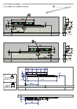
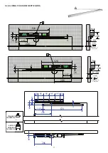
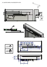
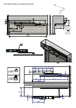
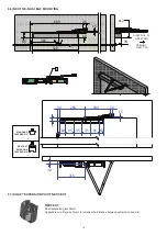
Depending on the type of arm to be used and the opening direction of the door, refer to the relevant technical drawing (para. 6 and sub-
paragraphs), which shows the installation dimensions.
Mount and secure the automation plate using screws and fixings suitable for the type of support (not supplied by Label).
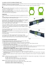
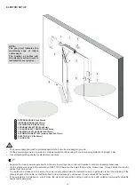
The automation NEXT-120S provides the possibility of connecting the arm pin on
both sides of the mechanical body.
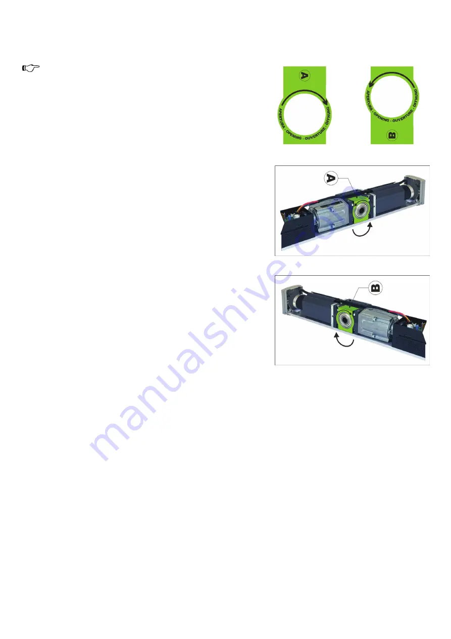
The arrow on the shaft output of the mechanical body indicates the opening
direction of the automation (Fig. 5).
Locate the correct side for connecting the pin according to the type of arm used
(pull or push) and the door opening direction.
WARNING!!!
The opening direction of the automation must match the opening direction of the
door.
If the arm rotates in the opposite direction to the opening direction, it can result in
irreversible damage to the automation latch spring.
For pull to open doors, reinstall the mechanical motor/spring unit onto the plate
with the letter A on the label visible from above, indicating that the automation
NEXT-120S is ready for installation on pull to open doors (Fig.A).
The arm models suitable for pull to open doors with wall mounted automation are
NEXT120‑BDT, NEXT120‑B150, NEXT120‑B250.
If you need to install the automation on push to open doors, reinstall the mechanical
motor/spring unit onto the plate on the opposite side with the letter B on the label
visible from above, indicating that the automation is ready for installation on push
to open doors (Fig.B).
The arm models suitable for push to open doors with wall mounted automation are
NEXT120‑BAS, NEXT120‑BDS.
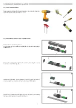
Install the motor/spring mechanic unit on the plate using the four socket head cap
screws M5x60.
Reinstall the enclosure of the electronic control unit and the plastic side caps on
the automation plate.
The automation NEXT 120S is supplied with the closing spring unloaded.
After installing the automation NEXT 120S, the spring loading procedure must
be performed before inserting the arm pin into the shaft output of the automation.
5.4) SPRING LOADING PROCEDURE
Carefully follow the following steps to load the spring of the automation NEXT 120S:
a) make sure that the arm is not inserted into the automation.
b) Select position "II" on the manual selector located on the side cap of the automation.
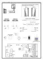
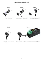
c) Supply the automation with 230V (see para. "Electrical connections" about how to connect the power terminal).
The control unit buzzer will emit 5 fast beeps.
d) Press and hold the button PS1 (start) on the electronic control unit NEXT‑L120S.
The buzzer of the control unit will emit 5 beeps and the gearmotor will perform a slow rotation of one turn in the direction of the arrow.
Once the maximum spring load position has been reached, the motor will stop and some beeps will sound.
Release the button PS1 (see
NOTE 1
).
WARNING! DO NOT REMOVE 230V POWER TO PREVENT SPRING UNLOAD.
e) Insert the arm pin into the shaft output of the automation, ensuring that the plastic plate is clipped onto the mechanical body and
secure it by tightening the central screw firmly (see
NOTE 2
).
f) Remove power from the automation and manually check the door movement for the entire run.
The leaf must close by means of the closing spring, even after a few degrees of opening, at a limited speed thanks to the passive
braking control circuit.
g) Start the automation by following the procedure described in paragraph "Initial SETUP of the automation" and selecting COMPLETE
SETUP.
NOTE 1:
if during the spring load turn described in item d) above the button PS1 is released, the movement stops. In this case, press
PS1 again to resume the loading turn.
To slowly unload the spring, select position 0 on the manual selector.
To quickly unload the spring back to its initial position, select position I.
NOTE 2:
When choosing the spring closure force, consider the following:
connect the arm with door open to achieve minimum force (recommended solution);
connect the arm with door closed for maximum force:
connect the arm with door at half run for intermediate force.
Fig.A
Fig.B
Fig.5

