83
HYDRAULIC UNIT
B
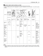
Hydraulic Control Unit Use Reference Chart
In order to handle the hydraulics properly, the operator must be familiar with the following.
Though this information may not be applicable to all types of implements and soil conditions, it is useful for general
conditions.
A
With an implement mounted, use the top hole of the top link holder to keep the implement as horizontal as possible,
and its center hole to keep the implement tilted forward. Only if the implement is not well matched, the lower hole may
be used.
Implement
Remarks
Soil condition
Top link mounting
holes
(1) Mode
selector
switch
(2) Hydraulic
control
lever
(3) Draft ratio
adjustment
dial
Gauge
wheel
(1) Telescopic
stabilizers
Moldboard
plow
Light soil
Medium soil
Heavy soil
2
Draft Control
(A)
Mixed draft
control
Place the
hydraulic
control lever
to the
suitable
position.
Turn the dial
to the suitable
position
YES/NO
Loose
Insert the
telescopic
stabilizer set-
pin through the
slot on the
outer tube that
align with one
of the holes on
the inner bar.
Disc plow
---
Harrower
(spike,
springtooth,
disc type)
---
Sub-
soiler..........
Weeder,
ridger......
---
1
Position
control
(B)
Position
Control
Place the
hydraulic
control lever
to the
suitable
position.
---
YES
Tighten
Telescopic
stabilizer
should be tight
enough to
prevent
excessive
implement
movement
when
implement is in
raised
position.
For
implements
with gauge
wheels, lower
the position
control lever
all way.
Earthmover,
digger,
scraper,
manure fork,
rear
carrier.........
YES/NO
Mower (mid-
and rear-
mount type)
Hayrake,
tedder.........
NO
Summary of Contents for M100GX
Page 17: ... 7 SAFE OPERATION 7 DANGER WARNING AND CAUTION LABELS ...
Page 18: ...SAFE OPERATION 8 ...
Page 19: ... 9 SAFE OPERATION ...
Page 20: ...SAFE OPERATION 10 ...
Page 21: ... 11 SAFE OPERATION ...


