34
922-20207011/1.0
Tip
If images appear on the wrong side of the sonar view (for example, objects on the
right appear on the left), then select one of the “Inverted” orientations.
b
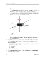
If you wish to create your own orientation, select
Custom
, then enter in the precise
pitch, roll, and yaw angles of the Sonar Head position.
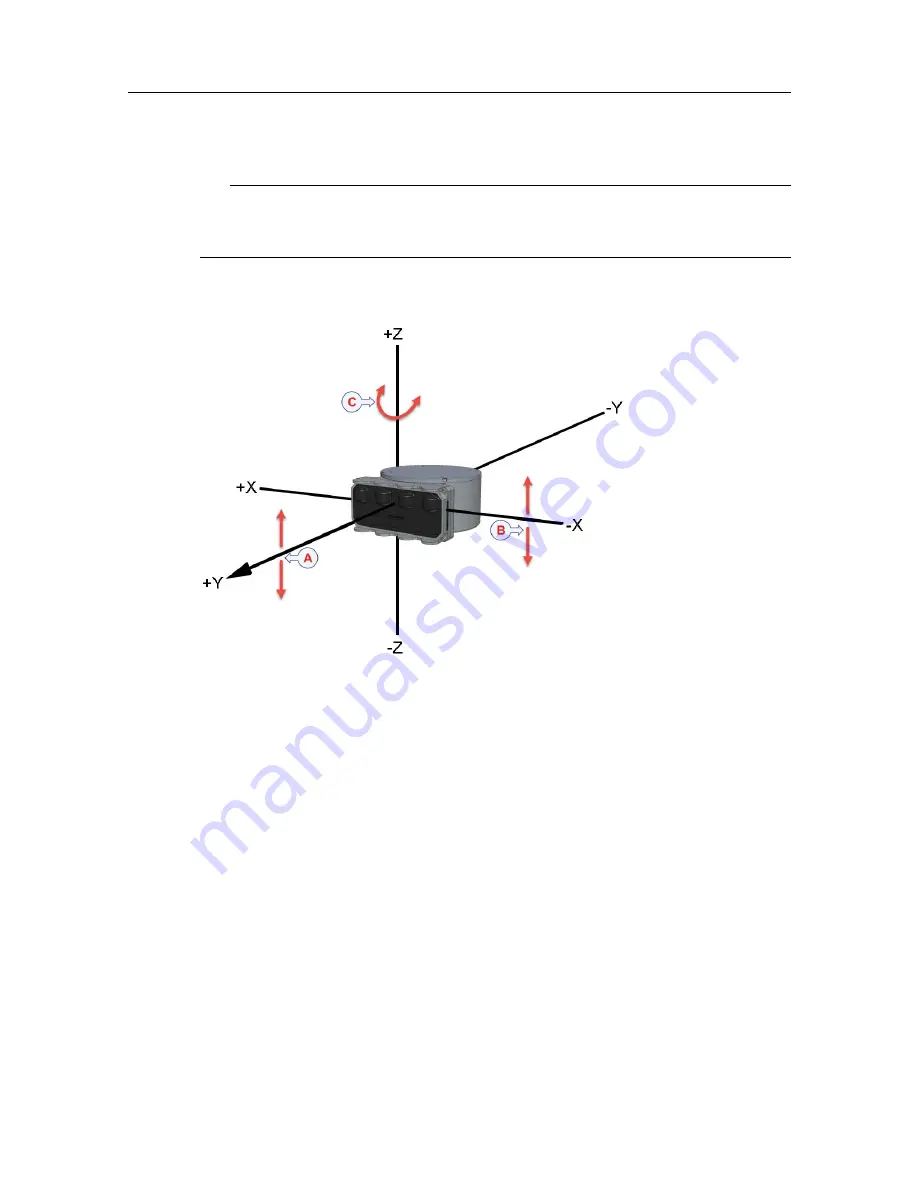
A
Pitch
B
Roll
C
Yaw
Positive pitch means bow up. Positive roll means starboard side down. Positive
yaw means starboard turn.
2
Measure the distance between the Sonar Head and your GPS or other position sensor.
You will need to measure the distance in terms of the Flexview coordinate system,
as shown in the image.
• The coordinate system’s Master Reference point is always assumed to be your GPS
or position sensor reference point.
• X = to starboard
• Y = forwards
• Z = pointing upwards
3
Enter these measurements into the X, Y, and Z Offset fields on the
Mounting Offsets
page in the Flexview software.
Flexview Installation Manual
Summary of Contents for Flexview
Page 1: ...Installation Manual Flexview Multibeam Sonar ...
Page 2: ......
Page 8: ...6 922 20207011 1 0 Flexview ...
Page 95: ...922 20207011 1 0 93 Flexview Sonar Head 500 kHz outline dimensions Drawing file ...
Page 96: ...94 922 20207011 1 0 Flexview Installation Manual ...
Page 97: ...922 20207011 1 0 95 Drawing file ...
Page 99: ...922 20207011 1 0 97 Drawing file ...
Page 100: ...98 922 20207011 1 0 Flexview Installation Manual ...
Page 126: ... 2019 Kongsberg Mesotech ...

