OPERATION AND MAINTENANCE MANUAL
DTR MCK v.2.4
PAGE
GDYNIA
MODULAR AIR HANDLING UNITS
MCKS, MCKH, MCKP
2017 EN
13/45
KLIMOR Spółka z ograniczon
ą
odpowiedzialno
ś
ci
ą
Sp.k., 81-035 Gdynia, ul. B. Krzywoustego 5
Fax: (+48 58) 783-98-88; Tel.: (+48 58) 783-99-99
Service -
Fax: (+48 58) 783-98-88; Tel.: (+48 58) 783-99-50/51 Mobile: (+48) 510 098 081
Information in this document is subject to change
email:
-
office
-
service
Table No. 9
The parameters required for correct setting of the rotor inverter
Rotor symbol
non-hygroscopic
Rotor symbol
hygroscopic
Min operation
frequency
of motor Fz min
[Hz]
Max motor opera-
tion frequency, FZ
max [Hz]
Rated motor
output
[kW]
Rated motor
RPM
[rpm]
Rated
motor cur-
rent
[A]
RR1_MCK01
RRH1_MCK01
5
47
0,06
214
0,4
RR1_MCK02
RRH1_MCK02
5
38
0,06
214
0,4
RR1_MCK03
RRH1_MCK03
5
38
0,06
214
0,4
RR2_MCK03
RRH2_MCK03
5
45
0,06
214
0,4
RR1_MCK04
RRH1_MCK04
5
50
0,06
214
0,4
RR2_MCK04
RRH2_MCK04
5
40
0,12
170
0,6
RR1_MCK05
RRH1_MCK05
5
50
0,06
214
0,4
RR2_MCK05
RRH2_MCK05
5
40
0,12
170
0,6
RR1_MCK06
RRH1_MCK06
5
40
0,19
170
0,8
RR1_MCK07
RRH1_MCK07
5
52
0,19
170
0,8
RR2_MCK07
RRH2_MCK07
5
40
0,19
170
0,8
RR1_MCK08
RRH1_MCK08
5
50
0,19
170
0,8
RR2_MCK08
RRH2_MCK08
5
50
0,19
170
0,8
RR1_MCK09
RRH1_MCK09
5
50
0,37
140
2,1
RR2_MCK09
RRH2_MCK09
5
50
0,37
140
2,1
RR1_MCK10
RRH1_MCK10
5
50
0,37
140
2,1
RR1_MCK11
RRH1_MCK11
5
50
0,37
140
2,1
RR2_MCK11
RRH2_MCK11
5
50
0,37
140
2,1
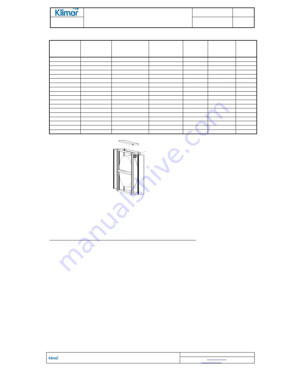
Figure No. 8
Recommended assembly of the inverter inside the rotor's block should be done according to the figure
The rotor is made of layers of aluminum foil wound over the rotation axis
–
alternately smooth and folded one, form-
ing channels for air flow. In order to recover latent heat due to the humidity difference, the foil is additionally covered
with a layer of hygroscopic material.
The heat exchanger should be equipped with anti-frost system to protect the unit against consequences of extensive
chilling of the air exhaust part of the exchanger.
The protection system consists of (at a delivery of the control system manufacturer):
- sensor (pressure gauge) of pressure difference upstream and downstream the exhaust air exchanger,
Once the assumed pressure drop at the pressure gauge is achieved, a controller sends a signal to the heat exchang-
er due to frosting of the exchanger, to decrease in a stepless manner the rotor RPMs (system with a inverter).
NOTE! The rotary heat exchanger block as standard is delivered without the anti-frost system. Type of the
system is determined by an AHU or control system designer. Pressure system is recommended.
2.3.2.8.
PR cross-flow heat exchanger block and high-performance hybrid CPR heat recovery system
Application of the cross-flow heat exchanger ensures heat recovery from the exhaust air with up to 70% efficiency
(PR sets) and up to 90% in the high-performance hybrid heat exchangers (CPR sets).
Main system elements: cross-flow or high-performance cross-flow heat exchanger, by-pass, two-stage air damper,
drip tray and droplet separator.
The cross-flow heat exchanger is made of thin, pressed aluminum plates making up channels for supplied and ex-
hausted air. A warm air stream extracted from a room flows through the heat exchanger channels and it heats up its
plates. The supply air stream flows perpendicular to the exhaust air stream, collecting heat from the heat exchanger's
plates.
Heat recovery with the cross-flow heat exchanger does not require providing external energy. The exchanger does
not feature moving parts such as, which makes it reliable and long-lasting. Supply and exhaust air streams are sepa-
rated from each other and in a result humidity, odors and contaminations do not transfer the system.
location of frequency converter


