


OPERATION AND MAINTENANCE MANUAL
DTR MCK v.2.4
PAGE
GDYNIA
MODULAR AIR HANDLING UNITS
MCKS, MCKH, MCKP
2017 EN
12/45
KLIMOR Spółka z ograniczon
ą
odpowiedzialno
ś
ci
ą
Sp.k., 81-035 Gdynia, ul. B. Krzywoustego 5
Fax: (+48 58) 783-98-88; Tel.: (+48 58) 783-99-99
Service -
Fax: (+48 58) 783-98-88; Tel.: (+48 58) 783-99-50/51 Mobile: (+48) 510 098 081
Information in this document is subject to change
email:
-
office
-
service
The section consists of a rotary heat exchanger and driving mechanism. The casing has got an inspection panel en-
abling access to the rotor's driving mechanism.
The hygroscopic heat exchangers may have got a tray installed under the exchanger, located within the AHU frame
free space, with a connector leading to the operational side of the AHU.
The driving mechanism consists of a belt transmission, electric motor and motor base with self-adjusting belt tension-
ing function.
The electric motor is delivered with a 0,37kW; 1×230V/3×230V; 50Hz inverter.
The internal AHUs are equipped with Danfoss FC51 inverters and external AHUs are equipped with LG IC5 inverters.
Below you can find inverter settings for the 0÷10V signal control from an external source for both inverter types.
Wiring of inverters according to their respective OMMs.
If the AHU has been delivered together with the Klimor control system, do not use these settings. Please use infor-
mation provided in corresponding control system OMMs.
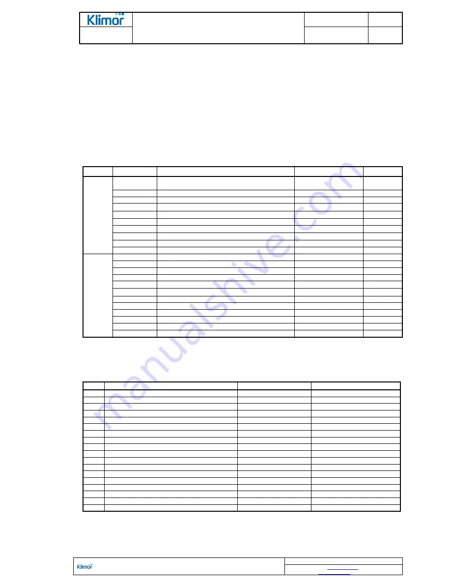
Table No. 7
Basic parameters for programming Danfoss FC 51 inverter
Settings for adjusting speed by analogue 0÷10V signal
Parameter no.
Parameter name
Setting
Unit
QUICK
MENU 1
120
Motor rated power
According to the motor
rating plate
kW
122
Motor rated voltage
230
V
123
Motor rated frequency
50
Hz
124
Rated current
Table No.
9
A
125
Motor rated RPM
Table No.
9
RPM
129
Auto matching with AMT motor
Switch on [2]
*/
302
Min set Hz value
FZ min
Table No.
9
Hz
303
Max set Hz value
FZ max
Table No.
9
Hz
341
Acceleration time in s - from min to max preset value
30
s
342
Breaking time in s - from min to max preset value
30
s
MAIN
MENU
190
Motor thermal protection
ETR Trip 1 [4]
315
Source 1 of the set value
1
316
Source 2 of the set value
0
317
Source 3 of the set value
0
412
Motor low speed limit in Hz
FZ min
Table No.
9
Hz
414
Motor high speed limit in Hz
FZ max
Table No.
9
Hz
416
Limit of torque in %
110
%
540
Relay function
6
610
Terminal 53 Low voltage level
0,07
V
611
Terminal 53 High voltage level
10
V
614
Terminal 53 Minimum set value
15
Hz
615
Terminal 53 Maximum set value
65
Hz
*/ Once this parameter is set to function [2] the PRESS HAND START message appear in the display. When the HAND START button on the control
panel is pressed, the converter proceeds with the auto matching.
When the auto matching is complete, press OK on the control panel and the parameter is automatically set to [0] value. Now you can proceed with the
programming.
Table No. 8
Basic parameters for programming LG IC5 inverter Settings for adjusting speed by analog 0÷10V signal
Code
Name
Set point value
Description
H93
Restoring factory defaults
1
All parameters
drv
Control mode
1
Switch ON -
forward
Frq
Frequency setting method
3
V1 terminal -
0÷10V
ACC
Acceleration time
30s
dEC
Stopping time
30s
F21
Max. output frequency
Fz max
Table
F22
Motor rated frequency
50 Hz
F23
Min requested frequency
Fz min
Table
F30
U/F characteristics
0
Linear
F50
Motor overload protection
1
Active
H30
Rated motor output
...kW
Table No. 9
H33
Rated motor current
...A
Table No. 9
I7
V1 min voltage input
0V
I8
Frequency for I7 input
Fz min Hz
Table No. 9
I9
V1 input max voltage
10V
I10
Frequency for I9 input
Fz max Hz
Table No. 9
I17
Determining P1 multifunction input function
0
Operation -
forward
I55
Relay function
12
Operation without alarm
NOTE!
The rotor drive motor has to be energized by an inverter in order to eliminate jerking a belt while starting and stopping the rotor.