166
Chapter 4 Remote Interface Reference
Using the APPLy Command
4
DC Offset Voltage
• For the offset parameter of the
APPLy
command, you can substitute
“MINimum”, “MAXimum”, or “DEFault” in place of a specific value
for the parameter. MIN selects the most negative dc offset voltage for
the function and amplitude specified. MAX selects the largest dc offset
for the function and amplitude specified. The default offset is 0 volts
for all functions.
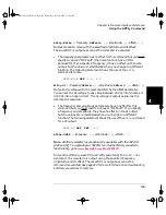
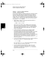
• Limits Due to Amplitude: The relationship between offset voltage and
output amplitude is shown below. Vmax is the maximum peak voltage
for the selected output termination (5 volts for a 50
Ω
load or 10 volts
for a high-impedance load).
|Voffset| < Vmax –
If the specified offset voltage is not valid, the function generator will
automatically adjust it to the maximum dc voltage allowed with the
amplitude specified. From the remote interface, a “Data out of range”
error will be generated and the offset will be adjusted as described.
• Limits Due to Output Termination: The offset limits are determined
by the current output termination setting (the
APPLy
command does
not change the termination setting). For example, if you set the offset
to 100 mVdc and then change the output termination from 50 ohms
to “high impedance”, the offset voltage displayed on the function
generator’s front-panel will double to 200 mVdc (and no error will
be generated). If you change from “high impedance” to 50 ohms,
the displayed offset will drop in half. See the
OUTP:LOAD
command on
page 181 for more information.
• Arbitrary Waveform Limitations: For arbitrary waveforms, the
maximum offset and amplitude will be limited if the waveform data
points do not span the full range of the output DAC (Digital-to-Analog
Converter). For example, the built-in “Sinc” waveform does not use
the full range of values between ±1 and therefore its maximum offset
is limited to 4.95 volts (into 50 ohms). The “0” DAC value is still used
as the offset reference even if the waveform data points do not span
the full range of the output DAC.
Vpp
2
-----------
33210A users guide.book Page 166 Wednesday, July 16, 2008 11:16 AM
Summary of Contents for 33210A
Page 1: ...Keysight 33210A 10 MHz Function Arbitrary Waveform Generator User s Guide ...
Page 2: ......
Page 3: ......
Page 14: ...12 Contents Contents 33210A users guide book Page 12 Wednesday July 16 2008 11 16 AM ...
Page 15: ...1 1 Quick Start 33210A users guide book Page 13 Wednesday July 16 2008 11 16 AM ...
Page 53: ...3 3 Features and Functions 33210A users guide book Page 51 Wednesday July 16 2008 11 16 AM ...
Page 273: ...5 5 Error Messages 33210A users guide book Page 271 Wednesday July 16 2008 11 16 AM ...
Page 301: ...6 6 Application Programs 33210A users guide book Page 299 Wednesday July 16 2008 11 16 AM ...
Page 311: ...7 7 Tutorial 33210A users guide book Page 309 Wednesday July 16 2008 11 16 AM ...
Page 335: ...8 8 Specifications 33210A users guide book Page 333 Wednesday July 16 2008 11 16 AM ...


