PBJ_N-SH-e-1810.docx
36
15
Balance assembly / dismantling precautions
15.1 Dismantling / Assembly
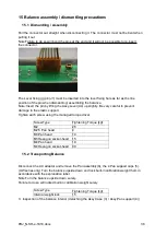
Pull the connector out straight when disconnecting it. The connector must not be bent when
pulling it out.
Note:Failure to do so will bend the pins at the end and it will not be possible to re-insert
the connector.
The Lever fixing jjg pin (J1) must be inserted into the lever fixing hole as far as the line
position of the pin when dismantling/ assembling the balance.
Note: Insert the pin by lifting the Assy,Lever(U4) up slightly. Be very careful to prevent
damage to the elastic support.
Tighten each screw using the managed torque driver.
Screw Type
Tightening Torque [kgf
・
cm]
M2
2.5
M2.5 Pan head
4
M3 Pan head
10
M3 Hexagon socket-head
bolt
15
M4 Pan head
18
M4 Hexagon socket-head
bolt
30
15.2 Transporting Balance
Disconnect the AC adaptor and remove the Pan assembly(6), the 4 Pan support caps (5).
(UW series only) Turn the balance upside down and lock built-in calibration weight them in
accordance with the explanation label.
Note:Turn the balance upside down surely.
Failure to do so will locked built-in calibration weight surely
Screw Type
Tightening Torque [kgf
・
cm]
Internal weight lock
15
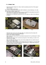
3. Inspection of the balance Interior (detaching the Assy,Case (3) / Assy,Pan support (4))
Summary of Contents for PBJ-N
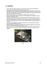
Page 4: ...PBJ_N SH e 1810 docx 4 ...
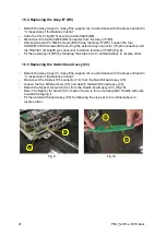
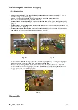
Page 40: ...PBJ_N SH e 1810 docx 40 Fig 7 Fig 8 ...
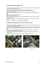
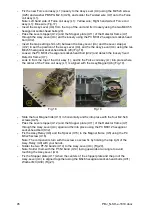
Page 47: ...47 PBJ_N SH e 1810 docx Fig 22 Fig 23 ...
Page 55: ...55 PBJ_N SH e 1810 docx 23 Drawing Fig 31 ...
Page 56: ...PBJ_N SH e 1810 docx 56 ...
Page 57: ...57 PBJ_N SH e 1810 docx Fig 33 ...

