


PBJ_N-SH-e-1810.docx
50
20.2 Adjustment of tilt errors
-
Detach the Assy,Case (3) in accordance with “3. Inspection of the Balance Interior”.
-
Adjust the level of the balance using the 3 Level adjusters (B2) while referring to the level
indicator, and then connect the AC adaptor to the balance.
-
Insert the Pan support cap (5) into the Assy,Pan support (4), and place the Pan assembly
(6) on top.
-
Load the following weights onto the Pan assembly (6) and press the -->0/T<-- key.
Model
Weight
UW / UX (Small pan)
250g
UW / UX (820H,1020H)
400g
UW /UX (Large pan)
4000g
-
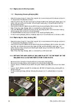
Insert a 1mm thick board under the two feet on the right hand side of the balance at the
front and rear. Read off the display while the balance is grounded like this (the right hand
side of the balance will be raised).
-
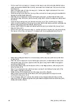
Loosen the M3 nut (L9) of the Assy,Lever (U4) if it does not meet the specification.(See
“Table 1 of 8.Performance Inspection”)
-
If the display is (+), turn the P4 M3x25 screw (L12) of the Assy,Lever (U4) in a clockwise
direction. If the display is (-), turn the P4 M3x25 screw (L12) of the Assy,Lever (U4)
counterclockwise.
-
Once adjustment is complete, lock the P4 M3x25 screw (L12) with the M3 nut
(L9)(Fig.27).
Fig.26
Fig.27
Summary of Contents for PBJ-N
Page 4: ...PBJ_N SH e 1810 docx 4 ...
Page 40: ...PBJ_N SH e 1810 docx 40 Fig 7 Fig 8 ...
Page 47: ...47 PBJ_N SH e 1810 docx Fig 22 Fig 23 ...
Page 55: ...55 PBJ_N SH e 1810 docx 23 Drawing Fig 31 ...
Page 56: ...PBJ_N SH e 1810 docx 56 ...
Page 57: ...57 PBJ_N SH e 1810 docx Fig 33 ...


