background image

55 


PBJ_N-SH-e-1810.docx 

23 

Drawing 


Fig.31 

Summary of Contents for PBJ-N

Page 1: ...mbH Ziegelei 1 D 72336 Balingen E Mail info kern sohn com Tel 49 0 7433 9933 0 Fax 49 0 7433 9933 149 Internet www kern sohn com Service Manual Precision balances KERN PBJ N Version 1 0 02 2018 GB PBJ_N SH e 1810 ...

Page 2: ...6 1 Testing upon acceptance 12 6 2 Packaging 12 7 Unpacking Setup and Commissioning 13 7 1 Installation Site Location of Use 13 7 2 Unpacking Scope of delivery 13 7 3 Placing 15 7 4 Mains connection 18 7 5 Switch power supply on 18 7 6 Connection of peripheral devices 19 7 7 Initial Commissioning 19 8 Adjustment 20 8 1 Manual adjustment by CAL button 20 8 2 Adjustment with internal weight 20 9 Adj...

Page 3: ...acement of the level 43 17 Replacing the Force coil assy L1 44 17 1 Dismantling 44 18 Assembly 44 19 Dismantling Assembling the Weight loader assy 10 46 19 1 Dismantling 46 19 2 Assembly 48 19 3 Adjustment of the pin height of the calibration weight loading 48 20 Balance Adjustment 49 20 1 Adjustment of the Assy Detector U8 Height 49 20 2 Adjustment of tilt errors 50 20 3 Adjustment of Corner Load...

Page 4: ...PBJ_N SH e 1810 docx 4 ...

Page 5: ...efore it can be used again in a statutorily regulated field Detailed instructions about conformity evaluated scales Repair must be carried only at 100 compliance with the type approval A violation of this specification will result in a loss of the type approval After successful repair the balance will have to be reverified before it can be used again in a statutorily regulated field 2 Introdution ...

Page 6: ...PBJ_N SH e 1810 docx 6 3 Appliance overview Models with readability d 0 001 g Models with readability d 0 01 g Windshield Weighing pan Display Keyboard Levelling screw ...

Page 7: ...ing Setting to zero No operation UNIT Switch over weighing unit 3 No operation PRINT Issue of weighing value to external appliances printer PC Issue of date and time to external appliances 1 This key is used to set a value when percent number of pieces PCS specific weight of solids d or specific weight of liquid d is displayed 3 Units different than g must be first set in the balance before they c...

Page 8: ... values Increases the numeric value of flashing digit by 1 No operation PRINT Entering numeric values To go to the next position No operation 3 3 Numeric entry Button Description Function Navigation button Increase flashing digit Navigation button Digit selection to the right Navigation button Confirm entry ESC Cancel input With numerical input the indicator appears SET indicates that the value ha...

Page 9: ...n until the last digit flashes Actuate the button again in order to call up the decimal point setting mode The reversed triangle symbol or the current decimal point flashes Actuate the button in order to move the decimal point to the required position by one digit each Actuate the button to define the position of the decimal point The message SEt which appears for a short period of time indicates ...

Page 10: ...Always shown when the menu is locked Asterisk Indicates that the displayed numeric value is not a mass value Communication symbol Is lit up during communication with external appliances via RS 232C cable Shown when communication functions are ON Inverse triangle symbol Indicates the setting of specific weight measurement It is used as an alternative to the decimal point 0 Zero indicator Animal sym...

Page 11: ...hing pan This may damage the measuring system Impacts and overloading exceeding the stated maximum load max of the balance minus a possibly existing tare load must be strictly avoided Balance may be damage by this Never operate balance in explosive environment The serial version is not explosion protected The structure of the balance may not be modified This may lead to incorrect weighing results ...

Page 12: ...tions 5 1 Pay attention to the instructions in the Operation Manual Carefully read this operation manual before setup and commissioning even if you are already familiar with KERN balances 5 2 Personnel training The appliance may only be operated and maintained by trained personnel 6 Transport and storage 6 1 Testing upon acceptance When receiving the appliance please check packaging immediately an...

Page 13: ...the balance against high humidity vapours and dust Do not expose the device to extreme dampness for longer periods of time Non permitted condensation condensation of air humidity on the appliance may occur if a cold appliance is taken to a considerably warmer environment In this case acclimatize the disconnected appliance for ca 2 hours at room temperature Avoid static charge of goods to be weighe...

Page 14: ...ccessories Models with readability d 0 001 g Models with readability d 0 01 g Mains adapter Operating instructions Menu overview Carrier weighing pan Protective cover Weighing pan 2 Fixiing screws Protection hood Wiindshield 2 screws Main weighing unit ...

Page 15: ...ansport screws clockwise until they are locked Mount safety hood Remove protective foil from adhesive strips and mount the safety hood so that it does not contact the weighing plate Levelling Turn in all three foot screws 1 as far as they go Slightly press down the left front side of the scale and turn out the two front foot screws until the air bubble 3 in the spirit level 2 is within the prescri...

Page 16: ... continuing to exert a slight pressure to the front side of the scale turn out the rear foot screw until the scale stands in stable position Check levelling regularly Installation of weighing plate Models with readability d 0 01 g ...

Page 17: ...0 docx Models with readability 0 001 g Remove rubber plug as shown in picture Attach wind guard and fix it by means of screws Install weighing pan as per illustration Note the correct position Place the wind guard cover ...

Page 18: ...stated voltage value must be the same as the local voltage Only use original KERN mains adapters Using other makes requires consent by KERN Models PBJ Prior to mains connection loosen the transport guard screws at the scale according to the sign in any case see chapter 7 3 7 5 Switch power supply on ...

Page 19: ...devices Interfaces at the balance back 1 RS 232C interface 2 DATA IO interface 3 AUX interface 4 DC IN connection 5 Keyboard interface 7 7 Initial Commissioning In order to obtain exact results with the electronic balances your balance must have reached the operating temperature see warming up time chap During this warming up time the balance must be connected to the power supply mains accumulator...

Page 20: ...measuring values it is also recommended to adjust the balance periodically in weighing operation Observe stable environmental conditions A warming up time see chapter 1 is required for stabilization Ensure that there are no objects on the weighing pan 8 1 Manual adjustment by CAL button The scales have been set by the manufacturer so that adjustment can be started directly from the weighing mode u...

Page 21: ...eisquelle konnte nicht gefunden werden 9 Adjustment test Activate function Press 3 times in weighing mode Menu group 1 Adjustment is displayed the indicator flashes Acknowledge by the current setting flashes Adjustment with internal weight I CAL only models PBJ see chap 8 1 1 Menu element 1 Adjustment test with internal weight I tESt only models PBJ see chap 8 2 2 Menu element 2 Adjustment with ex...

Page 22: ...e reused for applications subject to verification In weighing mode press E tESt is displayed If E tESt is not displayed press to return into weighing mode and activate menu element 4 see menu overview Press checking is started The displayed weight value of the recommended adjustment weight see chapter 1 flashes If the weight value shall be changed press the active digit flashes Carry out the desir...

Page 23: ...e press I tESt is displayed If i tESt is not displayed press to return into weighing mode and activate menu element 2 see menu overview Press checking is automatic Wait for a short period of time the difference to the previous adjustment is displayed Either Press the d value is reset to zero Adjustment of balance by resetting or Press the d value is not reset to zero No adjustment occurs ...

Page 24: ... times until A flashes Acknowledge with is used to change over among the following settings PSC on menu element 5 function activated PSC off menu element 6 function deactivated The current setting is marked by the stability display Acknowledge selection by Press repeatedly or for 3 s and the scale returns into weighing mode The flashing weight symbol signals that automatic adjustment is imminent I...

Page 25: ... to execute Clock Cal the following conditions must be met at the defined time If the conditions are not met within one minute adjustment is skipped The scale must be in weighing or standby mode The stability display must be indicated The load at the weighing plate must be near zero No other adjustment process must be started The weight symbol blinks for about two minutes as notification of span c...

Page 26: ...f a balance is used where obligation to verify exists as described above it must be verified and re verified at regular intervals Re verification of a balance is carried out according to the respective national regulations The validity for verification of balances in Germany is e g 2 years The legal regulation of the country where the balance is used must be observed Verification of the balance is...

Page 27: ...s facilitated by the numbering of the relevant menu elements For navigation in the menu please use the enclosed menu is displayed For navigation in the menu the symbol is displayed Call function Press 3 times in weighing mode The first menu group Adjustment is displayed the indicator flashes Select the required menu group by When pressing the relevant symbols flashes refer to the explanation below...

Page 28: ... measurement 6 S Setting of time and generation of an adjustment data set 7 Communication with external devices Making settings As an example the condition for evaluating the stability of 1 count menu element 27 to 4 counts menu element 29 shall be set Use the number and look for the function in the menu overview and make the following settings at the scale Call up menu group 3 the symbol E flashe...

Page 29: ...1 is the current setting Repeatedly press until Eb 4 menu element 29 is displayed Save by SET followed by the current setting Eb 4 is displayed characterized by the stability display Back to menu or onto weighing mode Actuate for a short time back to menu Actuate for a long time back to weighing mode ...

Page 30: ...e and wipe with a dry soft cloth Loose residue sample powder can be removed carefully with a brush or manual vacuum cleaner Spilled weighing goods must be removed immediately 12 2 Service maintenance The appliance may only be opened by trained service technicians who are authorized by KERN Before opening disconnect from power supply 12 3 Disposal Disposal of packaging and appliance must be carried...

Page 31: ...s been interrupted Operational measurement is allowed Too large error was found during calibration check Please contact your sales representative Too large error was found during calibration check Please contact your sales representative Menu lock active Menu lockout released The menu has been reset The contents of the new setting and factor have been saved Return in a result of mains failure The ...

Page 32: ... PCAL function Use the correct weight Large drift during calibration of the measuring range Use the correct weight Calibration weight is incorrect Use the correct weight Disturbances in the balance the balance is stopped when this display appears Received command code is incorrect Check limiters etc Total number of the displayed unit is longer than 7 positions Reduce load Disturbance in the balanc...

Page 33: ...isplay does not react after putting a weight on the scale pan The weighing pan is displaced Place the weighing pan correctly The display fluctuates Influence of vibrations or air flow Place the weight at the suitable location Try to change environment settings Protective shield is touching the scale pan Install the shield on the main unit of the balance Incorrect weighing result Calibration of the...

Page 34: ...rs OFF Press the ON OFF key once Now you are in weighing mode Enter the Service Mode following the same procedure as with standard models Pess the left end of the and the togehter for more than 3 seconds Press and together for more than 3 seconds and within 10 seconds after the first step System will display password entry Use the and the keys to enter the password to increase the highlighte digit...

Page 35: ...og digital converter value Service CAL writing in the simple linear coefficient Loading an unloading the build in calibration weight Initializing the build in calibration weight value EEPROM non volatile memory editor Calculating and wirting of the linear coefficient Calculating and wirting of the temperature coefficient EEPROM initialization Outputs the contents of the EEPROM Ends the service men...

Page 36: ...reful to prevent damage to the elastic support Tighten each screw using the managed torque driver Screw Type Tightening Torque kgf cm M2 2 5 M2 5 Pan head 4 M3 Pan head 10 M3 Hexagon socket head bolt 15 M4 Pan head 18 M4 Hexagon socket head bolt 30 15 2 Transporting Balance Disconnect the AC adaptor and remove the Pan assembly 6 the 4 Pan support caps 5 UW series only Turn the balance upside down ...

Page 37: ...11 6 24 Fig 2 Fig 3 Detach the Assy Case 3 from the Assy Base 2 and disconnect the Cable L105 connector 14 at the Assy Display B4 Fig 4 Remove the Calibration weight 9 Note Take care to ensure that the Calibration weight 9 does not get damaged or dirtied when removed Insert the Lever fixing pin J1 into the lever fixing hole of the Unit assy 1 down to the notch in the pin Fig 5 Note Insert the pin ...

Page 38: ...l to prevent damage to the elastic support Ensuring that the push up pin of the Weight loader assy 10 fits into the groove of the Calibration weight place the weight gently into the center of the Assy Pan support 4 Connect the Cable L105 connector 14 to the Assy Display B4 and put the Assy Case 3 over the Assy Base 2 Take care to ensure that the cable does not get caught in between Turn the balanc...

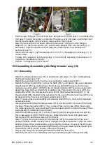
Page 39: ... 2 Replacing the Assy Analog B3 Detach the Assy Case 3 Assy Pan support 4 in accordance with the steps outlined in 3 Inspection of the Balance Interior Unscrew the three P4 M4x8 screws B10 fixing the Assy Display B4 in place and undo the CS 5 clip 15 which secures the Cable 45 B7 and the Weight loader assy 10 cable Next pull the connectors of the Weight loader assy 10 and Cable 45 B7 out at the As...

Page 40: ...PBJ_N SH e 1810 docx 40 Fig 7 Fig 8 ...

Page 41: ... I F B5 Fig 9 Fit the new Assy I F B5 by following the steps 2 to 4 outlined above in reverse order 16 5 Replacing the Switch board assy C3 Detach the Assy Case 3 Assy Pan support 4 in accordance with the steps outlined in 3 Inspection of the Balance Interior Disconnect the Cable L105 connector 14 from the Switch board assy C3 Loosen the five M3x6 screws C7 and detach the Switch board assy C3 Deta...

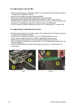
Page 42: ...ctor U8 by following the steps 2 to 5 outlined above in reverse order Conduct 7 1 Adjustment of the Assy Detector U8 Height 16 7 Replacing the Weight loader assy 10 UW series only Detach the Assy Case 3 Assy Pan support 4 in accordance with the steps outlined in 3 Inspection of the Balance Interior Undo the CS 5 clip 15 securing the Cable 45 B7 and the Weight loader assy 10 and disconnect the Cabl...

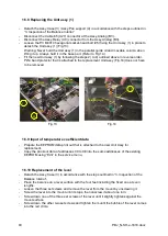
Page 43: ...to be removed Parallel Guide Movable Column 12 Parallel Guide 1 25 Fig 13 Fig 14 16 9 Input of temperature coefficient data Prepare the EEPROM data print out that is attached to the new Unit Assy for replacement Copy the print out data of addresses 00 to 0E into the same addresses of the existing EEPROM using Edit in the service menu 16 10 Replacement of the level Detach the Assy Case 3 in accorda...

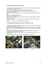
Page 44: ... fixing the Detector frame U7 in place to remove it Fig 16 Loosen the four M2 5x6 screws U25 fixing the four Magnet lids in place U13 and pull the Magnet lids U13 out horizontally to detach it Fig 16 U7 U13 U25 U32 U20 U4 25 U16 U9 U15 Fig 15 Fig 16 Loosen the two M4x55 hexagonal socket head bolts U20 fixing the Assy Lever U4 in place to remove the Assy Lever U4 from the top of the unit Remove the...

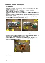
Page 45: ...d detach the loosely fixed Detector frame U7 Look in from the top of the Unit assy 1 and fix the Force coil assy L1 into place where the center of the Force coil assy L1 is aligned with the Assy Magnet U6 Fig 19 Fig 18 Fig 19 Slide the four Magnet lids U13 in horizontally and fix into place with the four M2 5x6 screws U25 Pass the Lever stopper U12 and the Stopper plate U11 of the Detector frame U...

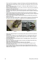
Page 46: ...At this point the Nut W14 can be loosened to detach the Assy Push up stick W28 In addition the Pull screw for the lever W5 the Washer M2 W20 the Compression spring W24 the Washer M2 Small W11 the Hooking shaft W6 bonded to the pull screw for the lever of the Detector lever W3 can be detached from the Lever calibration weight support W1 Note The Assy Push up stick W28 and Hooking shaft W6 etc must ...

Page 47: ...47 PBJ_N SH e 1810 docx Fig 22 Fig 23 ...

Page 48: ...erior 19 3 Adjustment of the pin height of the calibration weight loading Unlock the Transportation screws B11 in accordance with the explanation label Connect the Weight loader assy 10 connector to the Assy display B4 Connect the balance to the AC adaptor and turn on the power Select Ld_w built in calibration weight raised in the Service menu by following the procedures in 1 Operating Method for ...

Page 49: ...he Assy Detector U8 to a height where the voltmeter display inverts Fig 26 Note Adjustment target and guidance The absolute values of Assy Detector U8 output 3 5 0 5V both positive negative sides First balance the voltage by adjusting the height of Assy Detector U8 U8 movement Voltage balance Upwards Positive side gains Downwards Negative side gains Then adjust gain positive and negative sides at ...

Page 50: ...X Small pan 250g UW UX 820H 1020H 400g UW UX Large pan 4000g Insert a 1mm thick board under the two feet on the right hand side of the balance at the front and rear Read off the display while the balance is grounded like this the right hand side of the balance will be raised Loosen the M3 nut L9 of the Assy Lever U4 if it does not meet the specification See Table 1 of 8 Performance Inspection If t...

Page 51: ... Install PAN ASSY 6 Place the calibration weight Refer to Corner error Table 1 Chapter 8 and press O T key to zero the display center positions are shown in Fig 28 and record the reading of each position Grind slightly with the corner load adjustment tool J4 J5 the parts of the flexures corresponding to the off positions of the pan showing plus errors Note First adjust L R direction as this direct...

Page 52: ...er load error Prepare a weight as shown in table 1 Load the weight in turn on center of the pan 1 and positions 2 3 4 5 located off center of the pan and finally center 1 as shown in Fig 30 and take readings Operation is normal if the difference between the value obtained in the position away from the center and the value obtained in the center the corner load error is below the specification valu...

Page 53: ...ting in regular linear coefficients 21 5 Tilt error Load the weight as shown in table 1 and press the O T Insert a 1mm thick board under the two feet on the front side of the balance and take a B error B A If the error is large perform Adjustment of tilt errors TYPE PBJ 620 3NM PBJ 4200 2NM PBJ 6200 2NM PBJ 8200 1NM CAPACITY g 620 4200 6200 8200 Readability mg 1 10 10 100 Repeatability Rx Ry weigh...

Page 54: ... assy Adjustment of Corner Load Items to be prepared and order Service manual reference section 4 7 5 4 1 4 5 4 2 4 6 7 3 1 Height adjustment of Assy Detector 7 1 X X Digital multimeter DC 5 00V Check wire set 321 62356 2 Adjustment of tilt errors 7 2 X 3 Replacing EEPROM IC X 4 Inputting temperature coefficient into EEPROM 4 8 X EEPROM ReWriter When using a computer 5 Adjustment of linearity 13 X...

Page 55: ...55 PBJ_N SH e 1810 docx 23 Drawing Fig 31 ...

Page 56: ...PBJ_N SH e 1810 docx 56 ...

Page 57: ...57 PBJ_N SH e 1810 docx Fig 33 ...

Page 58: ...PBJ_N SH e 1810 docx 58 29 Fig 34 ...

Page 59: ...opper Lever U12 and or Assy Detector U8 are not correctly positioned Position Stopper Lever U12 correctly and adjust the height of Assy Detector U8 correctly Assy Analog B3 is failed Replace Assy Analog B3 Force coil assy L1 wire break earth leak Replace Force coil assy L1 Force coil assy L1 and Magnet assy U6 are contacting directly or with dusts Remove dusts and position Force coil assy L1 corre...

Page 60: ...heck drift and refer to f Drift Cable L65 U27 is disconnected damaged Connect Cable L65 U27 correctly Replace Cable L65 U27 Pt Ni band U14 is twisted bent badly soldered Replace Pt Ni band U14 Solder Pt Ni band U14 correctly Temp sensor assy M6 cable is badly soldered Solder Temp sensor assy M6 cable correctly The hole of Stopper plate U11 is contacting with the pin of Lever Assy Dusts exist betwe...

Page 61: ...ading control Controls the position working together with the calibration weight loading device Also controls the drive torque RS232C communications control Controls communication with PCs as an external peripheral via IC M105 The I O port controls communication with external printers It controls communication with external keys e g AKB301 for key port as well as having an external contact output ...

Page 62: ...ble connection port for communicating with external PCs etc 3 Printer port Mainly EP 80 EP 90 4 External input output port Input output dual use port The AKB 301 is usable during input mode Can be used as the contact output for the comparator during output mode Output is open collector TR 5 Extended communication port External communication port for future expansion options At present the RDB 201 ...

Page 63: ...led etc Display SvC_CAL in the Service menu Press The balance will enter a B state that allows the setting of provisional linear constants Ld30000 will flash Place a 30g weight for a small pan and 300g for a large pan and press when the stability mark illuminates Ld 0 flashes Take the weight off the pan and press when the stability mark appears With this the setting of a simple linear coefficient ...

Page 64: ...e Weight 1 100g 00100000 Weight 2 200g 00200000 Weight 3 300g 00300000 Weight 4 400g 00400000 Weight 5 500g 00500000 Weight 6 620g 00620000 For PBJ 4200 2NM Value of Weight Used Count Data Value Weight 1 500g 00050000 Weight 2 1000g 00100000 Weight 3 2000g 00200000 Weight 4 3000g 00300000 Weight 5 4000g 00400000 Weight 6 4200g 00420000 For PBJ 6200 2NM Value of Weight Used Count Data Value Weight ...

Page 65: ...ng capacity If the value does not amount to 8 digits fill in the higher digits with 0 The data obtained in step 2 above wAd count data values are written into storage registers 40 to 5B using Edit in the Service menu 1 item of data requires 4 storage registers The upper and lower digits of the count data values are stored in the first two storage registers and the upper and lower digits of the wAd...

Page 66: ...through the Service menu mode by repeatedly turning the key and the Edit mode is selected with the key the contents of the EEPROM will be displayed at the same time the storage register 10 will flash Repeatedly turn the to select 4 flashes registers numbered in the 40s are selected ...

Page 67: ... will flash By pressing the key at this point you will enter the register 42 data edit mode To alter the register repeat steps 1 2 3 above select the register with step 4 and change the data with step 5 Repeat this as necessary To renew the EEPROM non volatile memory data press the key down for more than 3 seconds until is displayed SET will appear after this and the data will be renewed To leave ...

Reviews: