PBJ_N-SH-e-1810.docx
44
17
Replacing the Force coil assy (L1)
17.1 Dismantling
-
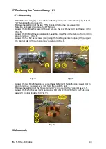
Detach the Unit assy (1) in accordance with the procedures outlined in steps 1) to 5) of
“4.7 Replacing the Unit assy(1)”.
-
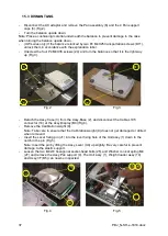
Remove the soldering of the two PT-NI bands (U14) on the Assy,Lever (U4).
Note: Do not break or damage the PT-NI band.
-
Loosen the P4 M3x25 screws (U16) and remove the Assy,Relay (U9) and Spacer (U15)
(Fig.15).
-
Loosen the P3 M3x10 hexagonal socket-head bolt (U22) fixing the Detector frame (U7) in
place to remove it (Fig.16).
-
Loosen the four M2.5x6 screws (U25) fixing the four Magnet lids in place (U13) and pull
the Magnet lids (U13) out horizontally to detach it (Fig.16).
U7
U13 U25
U32
U20
U4
25
U16
U9
U15
Fig.15
Fig.16
-
Loosen the two M4x55 hexagonal socket-head bolts (U20) fixing the Assy,Lever (U4) in
place to remove the Assy,Lever (U4) from the top of the unit.
-
Remove the soldering of the Twisted wire (U7) connected to the Force coil assy (L1).
-
Loosen the M2.5X6 screw (U25) and washer PB SPG M2.6 (U26) fixing the Force coil
assy (L1) in place to detach it (Fig.17).
Blue wire
Yellow wire U25 U26
U7
L1
Fig.17
18
Assembly
Summary of Contents for PBJ-N
Page 4: ...PBJ_N SH e 1810 docx 4 ...
Page 40: ...PBJ_N SH e 1810 docx 40 Fig 7 Fig 8 ...
Page 47: ...47 PBJ_N SH e 1810 docx Fig 22 Fig 23 ...
Page 55: ...55 PBJ_N SH e 1810 docx 23 Drawing Fig 31 ...
Page 56: ...PBJ_N SH e 1810 docx 56 ...
Page 57: ...57 PBJ_N SH e 1810 docx Fig 33 ...

