Section 3: Functions and features
Models 707B and 708B Switching Matrix Reference Manual
3-12
707B-901-01 Rev. A / August 2010
2.000000 2.000000 1.000000
Shows scan is running
(state = 2) and just
completed step 1 for scan
count of 2
2.000000 2.000000 2.000000
Shows scan is running
(state = 2) and just
completed step 2 for scan
count of 2
2.000000 2.000000 3.000000
Shows scan is running
(state = 2) and just
completed step 3 for scan
count of 2
2.000000 3.000000 1.000000
Shows scan is running
(state = 2) and just
completed step 1 for scan
count of 3
2.000000 3.000000 2.000000
Shows scan is running
(state = 2) and just
completed step 2 for scan
count of 3
6.000000 3.000000 3.000000
Shows scan has completed
(state = 6) and just
completed step 3 for scan
count of 3
NOTE
For more examples of using scanning and triggering, see the Models 707B and 708B User's Manual,
section "Using a Series 2600 with your Model 707B or 708B."
Hardware trigger modes
Use the hardware trigger modes to integrate Keithley Instruments and non-Keithley instruments into
an efficient test system. The hardware synchronization lines are classic trigger lines. The Model 707B
or 708B contains 14 digital I/O lines and three TSP-Link synchronization lines that you can use for
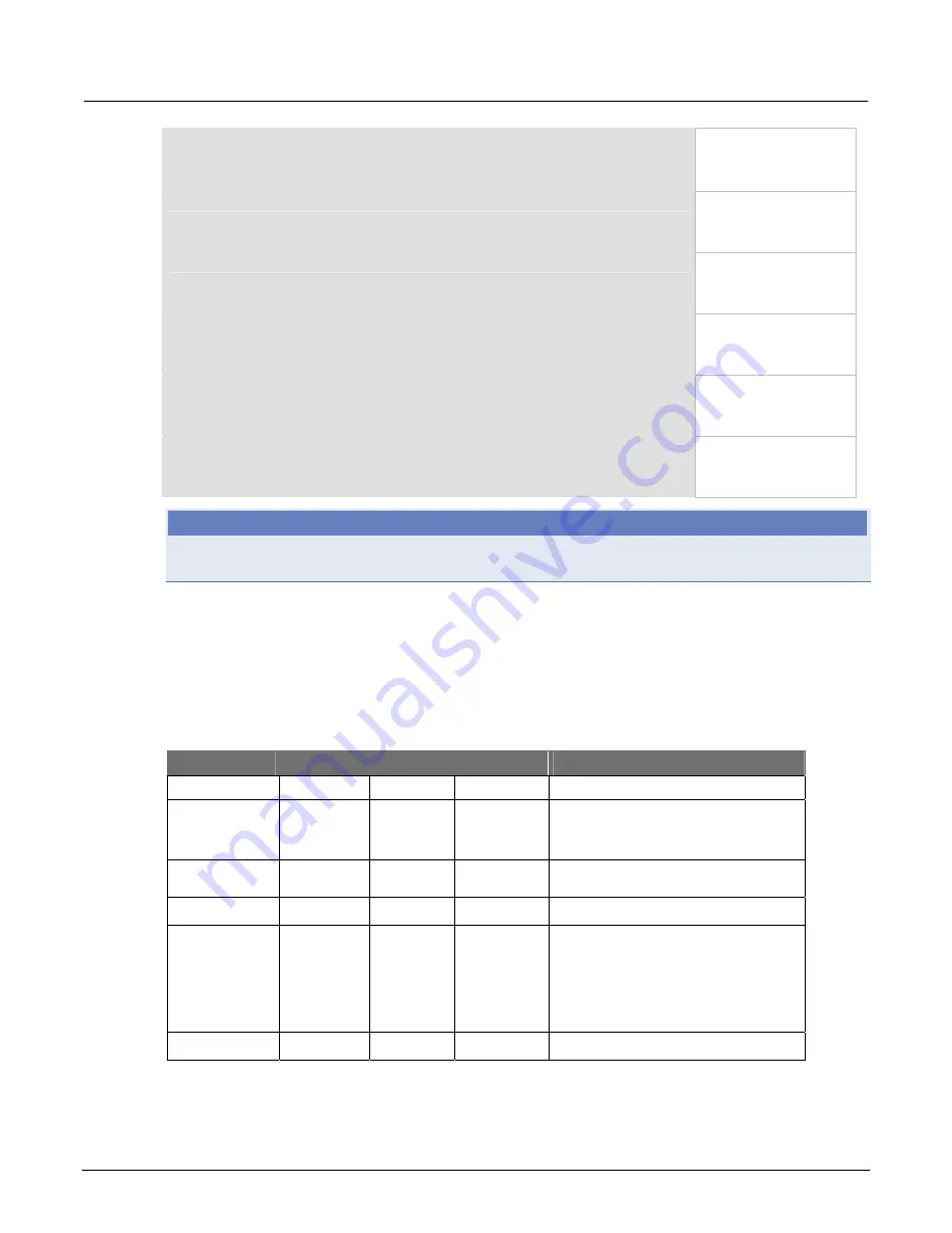
input or output triggering. The following table provides a summary for each hardware trigger mode.
Trigger mode
Output
Input
Notes
Unasserted Asserted Detects
Bypass N/A N/A N/A Use the
writetbit
and
writeport
commands for direct line control
Either edge
High
Low
Either
Short input pulses can cause a trigger
overrun
Falling edge
High
Low
Falling
Rising edge
N/A
N/A
N/A
•
The programmed state of the line
determines if the behavior is
similar to RisingA or RisingM
•
High similar to RisingA
•
Low similar to RisingM
Rising A
High
Low
Rising


