DN1237-0003 © 1997-2000 Kantech Systems Inc.
4 7
4 7
4 7
4 7
4 7
SECTION 7
SECTION 7
SECTION 7
SECTION 7
SECTION 7 - - P
- - P
- - P
- - P
- - P e r f
e r f
e r f
e r f
e r f o r
o r
o r
o r
o r m i n g M a n
m i n g M a n
m i n g M a n
m i n g M a n
m i n g M a n u a l O p e r
u a l O p e r
u a l O p e r
u a l O p e r
u a l O p e r aaaaa t i o n s
t i o n s
t i o n s
t i o n s
t i o n s
THE OPERATION MENU TOOLBAR
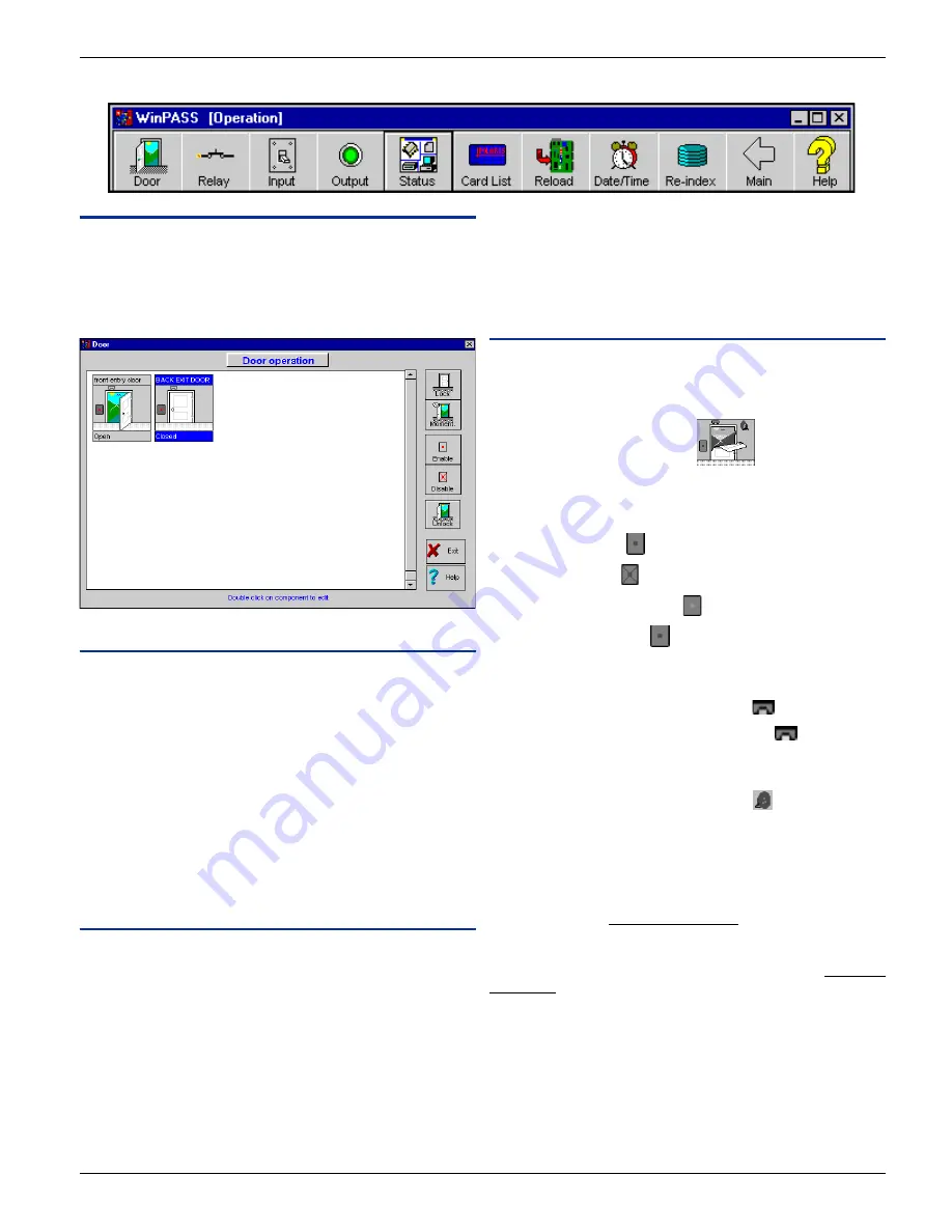
Door Operation
This window allows the operator to manually lock/unlock doors
and to enable/disable the readers. The graphical view displays the
door’ status and access events as they occur (you can actually see
the door open and close!).
Field Definition
Door name
Label identifying the door in the system. The door name is
displayed on top of each door drawing.
Door status
Door status is represented in text format here at the bottom of the
door drawing (i.e.: open, closed, forced open).
To select a door
To select a door just click on the selected door name and the name
of the door will be displayed in white capital letters highlighted
with a blue background. All manual operations are executed on
that selected door.
Buttons
Lock / Unlock
Select a door to be locked or unlocked, then click on the appropri-
ate button.
When the door is unlocked, the reader’ status light becomes green
and when locked the reader’ status light changes to red.
Momentarily Unlock
Select a door to be momentarily unlocked according to the
duration of the “unlock time on access”field programmed in “Door
Definition”. After this period the door will automatically re-lock.
Enable / Disable reader
Select a door on which the reader has to be enabled or disabled.
This command is useful in case of emergencies to instantly remove
access rights to all individual cardholders who usually have
access to that door.
Status
Door State
The door state is represented by a graphic of the door. The graphic
can display 3 door states: door open, door closed and door forced
open.
For example “door forced open”.
Reader State
The reader’ state is represented by a graphic of the reader. There
are 4 different states:
-
Enabled (red dot)
-
Disabled (red X)
-
Door unlocked (green dot)
-
Door locked (red dot)
.
Rex State
A door equipped with a REX (request-to-exit device) will display
a REX icon door drawing (enabled - grey)
.
The REX can be enabled or disabled (yellow)
.
Alarm State
The alarm state is represented by an annunciator. When the door
is in alarm, the red flasher drawing will appear
. The annunciator’s
color will change according to the alarm; red for top priority and
yellow for a pre-alarm.
Unknown State
The door is considered to be in the “Unknown State” when the
system has not communicated with the controller. Unknown state
is represented by a blue question mark on the door.
Communication State
Communication errors or failures are represented by a red ques-
tion mark on the door.


