LRWMANUAL 0918
KAM CONTROLS, INC.
28
T R O U B L E S H O O T I N G
DENSITY IN
4-20+
4-20-
GND
GND
GND
GND
485+
232-TXD
232-RXD
485-
DOUT1
GND
GND
CHS
POWER-
POWER+
LED2
TP1
LED1
TP3
GND
KAM LR
W
www
.KAM.com
ask
anengineer@k
am.com
Phone:
+1 (713) 784-0000
MADE IN USA
LRW™ Low Range Watercut
+1 713 784 0000
Made in the USA
www.KAM.com
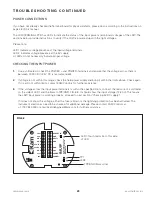
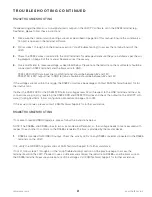
FIG 6-2 TERMINAL BOARD
FIG 6-1 LCD DISPLAY PLATE
Screws
LCD Connector
Turn off the field power supply to the LRW.
Use a 5/64 Allen wrench to remove the set screw on the display cover.
Turning it counterclockwise by hand, remove the display cover.
Remove the four (4) screws on the LCD display plate with a Phillips screwdriver (FIG 6-1).
Unplug the LCD connector from the terminal board (FIG 6-2) and set LCD display plate aside.
Remove the four (4) screws on the Terminal PCB with a Phillips screwdriver. FIG 6-2
Carefully pull the Terminal Board away from the Processor board by firmly holding it on the edges and pulling
straight up. Pulling the unit sideways or at an angle may damage the 26-pin connection.
Check for any fuses or surge protection devices visibly damaged on the bottom side of the Terminal PCB.
If the board passes a visual check, reinstall the Terminal PCB on the LRW by carefully aligning the 26-pin
header with its corresponding mating connector on the Processor board. Push directly down and then install
four (4) screws.
Connect the POWER+ and POWER- pins to the field power supply between 12-30V DC (+24V DC power is
preferred) if not already done
Turn on power to LRW.
1.
2.
4.
5.
6.
7.
8.
9.
10.
11.
3.
If the LCD display is off despite the LRW being powered on, please follow these instructions:


