LRWMANUAL 0918
KAM CONTROLS, INC.
29
If you have not already checked the Terminal board for physical defects, please do so according to the instructions on
page 28 of this manual.
The LRW TERMINAL PCB has LEDs to indicate the status of the input power and on board voltages of the LRW. The
sections below provide instructions to verify if the LRW is powered up with the right voltages.
Please note:
LED1 Indicates voltage presence at the input voltage terminals.
LED 2 Indicates voltage presence at the 5V supply.
Lit LEDs do not necessarily indicate proper voltage.
T R O U B L E S H O O T I N G C O N T I N U E D
POWER CONNECTIONS
CHECKING THE INPUT POWER
Use a voltmeter to check the POWER + and POWER - terminals and ensure that the voltage across them is
between 12-30 V DC (24 V DC is recommended).
If voltage is not within this range, check the field power supply and bring it within the limits above. Check again.
If it is still not within limits, contact KAM Controls for further assistance.
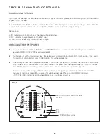
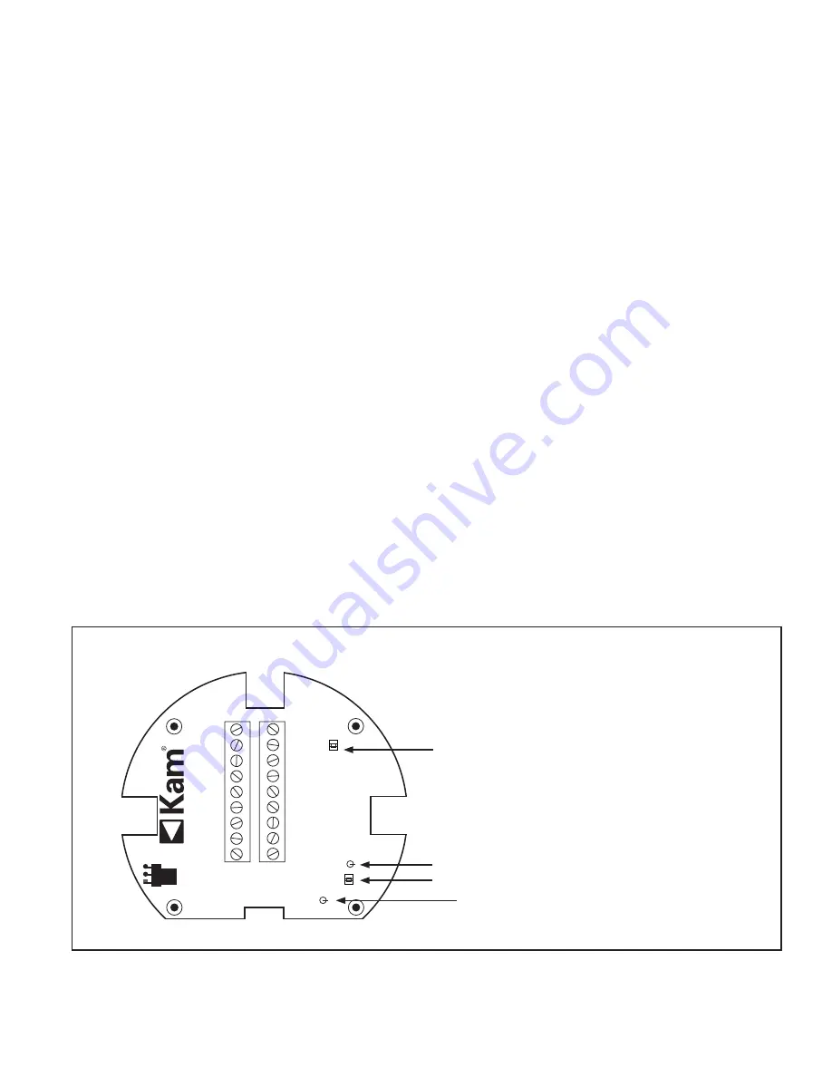
If the voltage across the input power terminals is within the specified limits, connect the red wire of a voltmeter
on the side of LED1 and the black to TP3/GND. FIG. 6-3. It should show the input voltage (12-30 V). This means
the LRW input power is working properly, proceed to next section ("Checking 5V DC supply").
If it does not show this voltage, either the fuse is blown or the lightning protection has been activated. The
instrument electronics need to be checked for additional damage. Please contact KAM Controls at
+1 713 784 0000 or email [email protected] for further assistance.
1.
2.
3.
DENSITY IN
4-20+
4-20-
GND
GND
GND
GND
485+
232-TXD
232-RXD
485-
DOUT1
GND
GND
CHS
POWER-
POWER+
LED2
TP1
LED1
TP3
GND
KAM LR
W
www
.KAM.com
ask
anengineer@k
am.com
Phone:
+1 (713) 784-0000
MADE IN USA
FIG 6-3
LED1: Touch red wire to this side
of LED
TP3/GND (black wire)
LED2
TP1

