LRWMANUAL 0918
KAM CONTROLS, INC.
5
I N S TA L L AT I O N
KAM HIGHLY RECOMMENDS VERTICAL INSTALLATIONS WHEREVER POSSIBLE FOR OPTIMAL MIXING.
PLEASE NOTE: In all KAM LRW Installations, the user should ensure that the KAM LRW is installed in a turbulent
flow with the Reynolds Number above 2000. Additionally, all KAM LRW's should be installed in accordance with API
MPMS Chapter 8, Section 2, Table 1, and in accordance with KAM mixing recommendations.
INSTALLATION FLOW REQUIREMENTS
Remove all the protective packaging materials, and ensure that the LRW
®
sensor was not damaged
during transit.
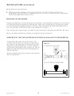
It is always recommended that the LRW NOT be installed in direct sunlight, and in high-ambient-temperature
installations that it be installed with recommended sunshade.
In cold weather, if LRW is exposed to an open environment, KAM CONTROLS recommends operators insulate
the LRW, and if the pipeline is heated that the heating trace be extended to include the LRW.
If the pipeline is not going to flow for extended amount of time and the pipe is not heated then LRW should be
taken out to avoid damage to the sensor probe by freezing water.
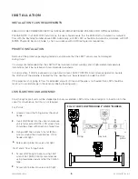
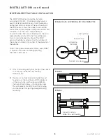
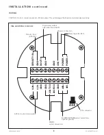
Flow through (spool) units will be shipped partionally assembled. LRW unit can be wired prior to insertion into the
spool for convenience, but this is not required.
For 2" units:
Grease around the O-ring below the small
flange.
Insert LRW body into the spool and ensure
unit is fully seated. NOTE: LCD screen face
should be alined with direction of pipe flow.
Using a 5/8" Allen wrench, install (8) hex
screws around the circumference of the
flange until tight.
Screw pitot probe into valve until tight.
PRIOR TO INSTALLATION
LRW FLOW THROUGH ASSEMBLY
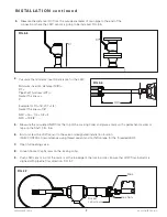
For 3" and 4" flow through units:
Screw LRW body into spool using 1 3/4"
wrench flat. KAM Controls recommends
using liquid pipe sealant rather than teflon
tape.
Screw pitot probe into valvue until tight.
Pitot
probe
Hex nuts
O-ring
1.
2.
3.
4.
1.
2.
FIG. 3-1 LRW FLOW THROUGH 2" AND 3" MODELS

