LRWMANUAL 0918
KAM CONTROLS, INC.
8
REMOVING THE LRW
®
SENSOR FROM FLOW THROUGH SPOOLS WITH FIXED INSERTION
To remove the LRW
®
sensor, first shut off power to the
instrument. Discontinue flow in loop from the main line and
drain fluid from loop. The probe can removed from the hous-
ing by removing the 5/8" hex screws on collar (2" models) or
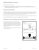
unscrewed from spool body (3" and 4" models). FIG. 3-8. The
probe can then be lifted from the cell for testing/inspection/
calibration purposes.
Removal should be conducted in accordance with all regional
and Class requirements.
FIG. 3-8
I N S TA L L AT I O N c o n t i n u e d
REMOVING THE LRW SENSOR
To remove the LRW sensor, first shut off power to the instrument. Loosen the Socket Cap Screws on the Lock Down
Collar. Slide the LRW sensor upward until the probe rests inside the seal housing. There is a mechanical stop when
the unit is fully retracted. Retighten the Socket Cap Screws. Next, close the Full-opening Ball Valve tightly. Drain oil
from valve if possible. The LRW sensor may now be unbolted from the system.
Note: If line pressure exceeds 100 psi, use a KAM
®
IT Insertion Tool when installing/removing the KAM
®
LRW sensor.
Removal should be conducted in accordance with all regional and Class requirements.
Re-tighten the Socket Cap Screws.
Tighten the hex nuts holding down the Locking Collar one half turn. (FIG. 3-7) These should never be
over-tightened. Their major function is to apply light pressure on the chevron packing to ensure a seal between
the seal housing body and the insertion shaft.
10.
11.
Hex screws
2" LRW flow through model
3" and 4" LRW flow through models

