


5
Remove the protective sheet attached
to the lens.
Note :
0
If there is a possibility that the lens may be
scratched while work is in progress, remove the
protective sheet only when you are about to turn
on the power. In this case, make sure that the
sheet is removed before the power is turned on.
6
Connect the LAN cable.
0
Connect the camera to a hub or computer
using a LAN cable.
0
When connecting to a hub: Make use of a
straight cable.
0
When connecting to a computer: Make use
of a cross cable.
When using PoE
0
Connect to the PoE power supply using a
LAN cable.
0
The red LED lights up when power is
supplied.
0
Use the PoE power supply while ensuring
that it is properly grounded.
LAN cable to use
0
STP (Recommended shield cable)
0
Length of 100 m or shorter
0
Category 5e and above
Note :
0
Cross cables cannot be used with some
computers. When connecting the camera
directly to a computer, check the computer’s
LAN specifications in advance.
0
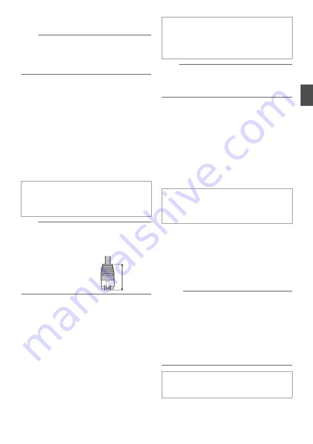
Use a LAN cable of which
the length of the connector
is less than 35 mm. If it is
more than 35 mm, the
camera housing cannot be
attached to the camera.
7
Connect the alarm signal cable to the
alarm signal terminal.
0
Connect the alarm signal terminal to external
devices, such as a sensor or buzzer.
0
For details on alarm signal names, refer to
the following.
0
For more details on alarm input/output, refer
to the following.
p.13 [Alarm Input/Output Signal] )
A
Peel off about 4 mm of the alarm signal cable
covering, and insert the cable into the I/O
connector.
Less than
35 mm
Alarm signal cable to use
0
Length of 50 m or shorter
0
UL1007, UL1015 or equivalent products
0
AWG#28 to AWG#20 or equivalent
products
Note :
0
Noises from an external source may cause the
camera to malfunction even when the cable
used is within 50 m. In this case, move the cable
away from the noise source.
8
Connect the audio cable.
0
Get ready a separate cable for connecting to
the audio device.
0
For details on audio signal names, refer to
the following.
AUDIO IN
: Connect with the cable from
devices such as a capacitor
microphone that supports
plug-in power.
AUDIO OUT : Connect with the cable from
devices such as speakers with
a built-in amplifier.
Cable for connecting to the audio device
(microphone input/line output)
0
Shielded cable recommended
0
Length of 5 m or shorter recommended
9
Connect the monitor cable.
0
It is not necessary to connect the monitor
cable if the monitor output is not used.
0
Please get ready a BNC cable separately
beforehand.
0
Connect the supplied monitor cable to the
monitor output terminal of this unit, and use
a BNC cable to connect the monitor cable
and the monitor.
Memo :
0
Secure the monitor cable such that it does not
fall out of the terminal when in use.
0
To use the monitor output, set monitor output on
the [Encoding] page to “ON”.
0
When the monitor in use has a wide display area,
lines may appear at the peripheral area of the
screen.
0
When the camera is mounted on a desktop, the
monitor output image will appear inverted even
when [Installation Mode] is set to “Desktop”.
Preparation for installation and connection is
now complete. Next, mount the camera unit.
Installation and Connection Preparations
19
Moun
tin
g
the
Ca
m
era


