background image

– 25 –

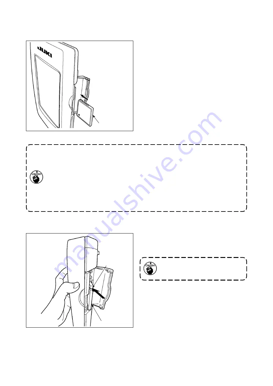
4)  CompactFlash (TM) 

1)  Turn the label side of the CompactFlash(TM) 

to this side (place the notch of the edge to the 
rear.) and insert the part that has a small hole 
into the panel.

2)  After completion of setting of the Compact-

Flash(TM), close the cover. By closing the 
cover, it is possible to access. If the Compact-
Flash(TM) and the cover come in contact with 
each other and the cover is not closed, check 
the following matters.

  Check that the CompactFlash(TM) is se-

curely pressed until it goes no further.

  Check that the inserting direction of the 

CompactFlash(TM) is proper. 


1.  When the inserting direction is wrong, panel or CompactFlash (TM) may be 

damaged.


2.  Do not insert any item other than the CompactFlash (TM).


3.  The media slot in the IP-420 accommodates to the CompactFlash (TM) of 2 GB or 

less.


4.  The media slot in the IP-420 supports the FAT16 which is the format of the 

CompactFlash (TM). FAT32 is not supported.


5.  Be sure to use the CompactFlash (TM) which is formatted with IP-420. For the 

formatting procedure of the CompactFlash (TM), see 

"II-2-31. Performing formatting 

of the media", p.91

.

CompactFlash (TM)

 Inserting the CompactFlash (TM)

 Removing the CompactFlash (TM)

1)  Hold the panel by hand, open the cover, and 

press the CompactFlash(TM) 

 removing 

lever 

. The CompactFlash(TM) is eject.

When the lever 

 is strongly pressed, 

the CompactFlash (TM) 

 may be bro-

ken by protruding and falling.

2)  When the CompactFlash(TM) 

 is drawn out 

as it is, removing is completed.

Summary of Contents for AP-874/IP-420

Page 1: ...1 ENGLISH INSTRUCTION MANUAL AP 874 IP 420 CompactFlash TM is the registered trademark of SanDisk Corporation U S A ...

Page 2: ...Installing the guide bar 12 3 15 Break in operation 12 4 OPERATION 13 4 1 How to install the needle 13 4 2 Threading the needle thread 14 4 3 Installing removing the bobbin case 15 4 4 Setting a bobbin into the bobbin case 15 4 5 Winding a bobbin 16 4 6 Thread tension 18 4 7 Thread take up spring 19 4 8 Adjustment procedure for the pocket setting device 20 4 9 Operation procedure 22 5 EMERGENCY ST...

Page 3: ... 1 Pattern button data input screen 57 2 Sewing screen 59 2 20 Performing pattern button No selection 61 1 Selection from the data input screen 61 2 Selection by means of the shortcut button 62 2 21 Changing contents of pattern button 63 2 22 Copying pattern button 64 2 23 Changing sewing mode 65 2 24 LCD display section at the time of combination sewing 66 1 Pattern input screen 66 2 Sewing scree...

Page 4: ...ing the height of the needle bar 105 1 2 Needle and hook adjustment 105 1 3 Counter knife 106 1 4 Positioning the counter knife and the knife thread guide 107 1 5 Thread take up amount adjustment 107 1 6 Holder pressure adjustment 107 1 7 Hook oil amount track of oil adjustment 108 1 8 Adjusting the oil amount in the face plate 109 1 9 Replacing the oil in the machine head 110 1 10 Cleaning the va...

Page 5: ...s 13 Dimensions 1 890 mm W x 1 510 mm L x 1 155 mm H excluding the thread stand 14 Temporary stop function It is possible to stop the sewing machine during sewing 15 Bobbin counter Up down method 0 to 9999 16 Sewing counter Up down method 0 to 9999 17 Stitch number counter Up down method 0 to 9999 18 Memory backup amount Patterns are automatically stored in memory at the time of power shutdown 19 ...

Page 6: ...al box Power switch Stacker Bobbin winder Thread stand Presser arm Start switch Emergency stop switch Temporary stop switch Presser plunger Pedal 2 CONFIGURATION If emergency stop switch is pressed while the device is in operation the blower motor will not stop but the power to the device will be turned OFF and the device will stop ...

Page 7: ... caster idles 3 After the machine has been set up properly tighten nut and fix level adjuster 3 INSTALLATION 3 1 Setting up the machine 1 Fix stacker safety pipe on the main body by means of pipe clamp and setscrews 2 Insert two pipes into pipe joint and fix with screws and nuts 3 2 Assembling the stacker safety pipe ...

Page 8: ...ressed after the removal of the sewing product the screen is changed over to the sewing screen and the stacker presser lever closes Sewing screen Stacker release screen A B 2 Adjust the stacking quantity by loosening the screw of sensor of work clamp cylinder and chang ing the sensor position Stacking quantity will be increased by moving the sensor position upward The sensor should be adjusted so ...

Page 9: ... operating air pressure should be set to 0 5 MPa 2 Deliberately open valve 3 Lift regulator knob in direction A Turning it in this state will change the sup ply air pressure Turn knob in direction C or in direction D so that black point of pressure gauge indicates 0 5 MPa After the adjustment lower knob in direction B to securely lock it 5 Pressure drop signal adjustment 1 Set the pressure at whic...

Page 10: ...d stand rob into thread stand thread guide 3 Tighten lock nut so that the thread stand will not be able to move 4 If ceiling wiring is possible pass the power cord through thread stand rod 3 4 Thread stand assembly 3 5 Installing the operation panel 1 Loosen cord clamp Remove panel cord ...

Page 11: ...el mounting base and fix it that position with set screws Bundle operation panel cord with cord clamp Fix operation panel mounting base supplied with the unit in position with setscrews 4 Open cover of the IP 420 Insert cable into the IP 420 5 Route cable down along the IP 420 and close cover 6 Place the IP 420 on operation panel mounting base 2 Remove setscrews Fix operation panel cable support b...

Page 12: ...ine is not supplied with a power plug It is therefore necessary for you to select a plug that matches the receptacle available under a given operating environment and attach it to the power cable 2 Two different kinds of power sources i e the 3 phase one and the single phase one are prepared for this machine Use the power source which matches the electric voltage specification of the machine 3 7 C...

Page 13: ... 9 1 Connect connector of pedal supplied with the unit to pedal junction connector 3 8 Installing the foot pedal 2 Install pedal ground wire on solenoid valve mounting plate with ground wire setscrew ...

Page 14: ...p switch is strongly pressed as far as it goes the switch is placed in its ON state When the button is turned clockwise the switch is placed in its OFF state Check to be sure that emergency stop switch is in its OFF state If emergency stop switch is in its ON state the op eration panel screen will not light up even if the power switch is turned ON Emergency stop switch OFF state Emergency stop swi...

Page 15: ...displayed on the operation panel press Reset button B 4 After pocket setting plate has reached its upper end remove foamed polystyrene from the pock et setting plate and turn the power OFF 3 12 Installing the label vacuum device Label suction opening is fixed with adhesive tape When using labels for sewing remove adhesive tape and turn the suction opening upward Adjust the position of the suction ...

Page 16: ...ess the key to run the machine at the number of revolu tions you have set At this time the number of revolutions measured by the machine is displayed on D Press reset button E to stop the sewing machine Set the number of revolutions for the break in operation at 2000 3 14 Installing the guide bar Securely insert the thread guide bar into the hole in the top cover in the orientation as shown in the...

Page 17: ...deeply into the hole in the needle bar in the direction of the arrow until it hits the sur face at the far end of the hole 4 Tighten the needle setscrew very tightly 5 Check to make sure that long groove B of the nee dle is on the face plate side 4 OPERATION WARNING Turn OFF the power before starting the work so as to prevent accidents caused by abrupt start of the sewing machine 4 1 How to instal...

Page 18: ...that passes through the needle 3 For threading the thread while power is ON please refer to the section on threading WARNING Turn OFF the power before starting the work so as to prevent accidents caused by abrupt start of the sewing machine 4 2 Threading the needle thread Pass the thread over the front side of the disc of thread guide ...

Page 19: ...t of the sewing machine 4 3 Installing removing the bobbin case A B C D 4 4 Setting a bobbin into the bobbin case Please use the accessory exclusive bobbin case Also if it is not pushed in far enough bobbin case might fall out during sewing So be careful 1 Hold the bobbin in a way that the thread open end is directed to the right as observed from you and set the bobbin into the bobbin case 2 Pass ...

Page 20: ...n of the bobbin presser Moving the bobbin presser in the direction of arrow F will increase the amount of thread to be wound round the bobbin 4 5 Winding a bobbin D E F 1 The bobbin winder will not actuate unless breaker of the seesaw type switch is in its ON state where the white engraved marker dot can be observed It means that you can use breaker as the bobbin winder switch 2 There are times wh...

Page 21: ...r stopping the winder 2 Restoring the bobbin winder to operation after it stops 1 First flip bobbin presser in the direction of arrow B then turn the bobbin winder switch OFF 2 Remove the cause of the force that tends to stop the thread from winding 3 Temporarily flip the circuit protector switch from po sition C to D then return it to C 4 Step 3 restores the circuit protector to its original stat...

Page 22: ... thread re maining is increased 3 Thread guide rod should apply as little tension as possible 4 6 Thread tension Data input screen Sewing screen 4 Tension controller No 2 is an AT thread con troller Thread tension controlled by this control ler is changed on the operation panel It can be changed on the data input screen blue back ground and the sewing screen green back ground The thread tension ca...

Page 23: ...oove in tension post and turn the tension post clockwise in di rection A to increase the pressure of thread take up spring or counterclockwise in direction B to decrease it 4 7 Thread take up spring 1 When adjusting the stroke of thread take up spring the position of the thread breakage de tecting plate should also be adjusted Adjust the position of the thread breakage detecting plate so that it a...

Page 24: ...ng plate Press B to change the mode from the automatic mode to the step mode 2 Loosen two nuts Adjust with stopper bolts the lift of the pocket setting plate 3 Press the start button to lower the pocket setting plate Check the clearance between the top surface of the table and the pocket support plate Reference height for adjustment Adjust so that a clearance through which a garment body is allowe...

Page 25: ...automatic mode to the step mode 2 Press the start button to lower pocket setting plate to its intermediate position 3 Loosen four screws to remove cover 4 Loosen intermediate position sensor and move it 5 Press A to lower pocket setting plate from its upper end to its intermediate position Check the intermediate position 6 Tighten intermediate position sensor Install cover and tighten four screws ...

Page 26: ... the machine by hand Remove your hands from the garment body and depress left pedal to lower pocket setting plate Place a pocket cloth on the pocket setting plate while keeping the pedal held depressed The pocket setting plate goes up by releasing the left pedal to allow you to re place the garment body Be aware that the pocket setting plate comes down when you depress the pedal Carefully protect ...

Page 27: ...tton is turned clockwise the switch is placed in its OFF state When emergency stop switch is placed in its ON state the power to the machine parts excluding the blower motor is disconnected to stop them To disconnect the power for any purpose other than turning OFF of the emergency stop switch operate the power switch 2 Precautions for use of the emergency stop switch If emergency stop switch is i...

Page 28: ...sert the media to IP 420 and select Pattern No II OPERATION SECTION WITH REGARD TO THE PANEL Pattern name Description Users pattern Pattern that can be stored in the body Max 999 patterns can be registered Vector format data File that extension is VDT Read from media Max 999 patterns can be used 3 Folder structure of the media Store each file in the directories below of the media Data that are not...

Page 29: ... CompactFlash TM may be damaged 2 Do not insert any item other than the CompactFlash TM 3 The media slot in the IP 420 accommodates to the CompactFlash TM of 2 GB or less 4 The media slot in the IP 420 supports the FAT16 which is the format of the CompactFlash TM FAT32 is not supported 5 Be sure to use the CompactFlash TM which is formatted with IP 420 For the formatting procedure of the CompactFl...

Page 30: ... Put the cover back in place Cautions when using the media Do not wet or touch it with wet hands Fire or electric shock will be caused Do not bend or apply strong force or shock to it Never perform disassembling or remodeling of it Do not put the metal to the contact part of it Data may be disappeared Avoid storing or using it in the places below Place of high temperature or humidity Place of dew ...

Page 31: ...SB terminal on the IP panel until it will go no further Do not turn the power OFF while the data on the USB flash drive is being accessed USB specifications Conform to USB 1 1 standard Applicable devices 1 Storage devices such as USB memory USB hub FDD and card reader Not applicable devices CD drive DVD drive MO drive tape drive etc Format supported FD floppy disk FAT 12 Others USB memory etc FAT ...

Page 32: ...the informa tion screen can be performed COMMUNICATION key Changeover of the data input screen and the communi cation screen can be performed MODE key Changeover of the data input screen and the mode changeover screen which performs various detail set tings can be performed Contrast control Brightness control CompactFlash TM eject button CompactFlash TM slot Cover detection switch Connector for ex...

Page 33: ...e display in the upward direction DOWN SCROLL button This button scrolls the button or the display in the downward direction RESET button This button performs the release of error NUMERAL INPUT button This button displays ten keys and input of numerals can be performed CHARACTER INPUT button This button displays the character input screen Refer to II 2 17 Naming users pattern p 55 RESSER LOWERING ...

Page 34: ...tion screen is displayed Set the language you use It is possible to change with Memory switch When ending the selection screen with CANCEL button or ENTER button without performing the language selection the language selection screen is displayed whenever the power is turned ON Select the pattern No you desire to sew When the power is turned ON the data input screen is dis played If pattern select...

Page 35: ...button Pattern button name input screen is displayed Refer to II 2 17 Naming users pattern p 55 D PRESSER DOWN button The presser plunger comes down and the presser down screen is displayed Refer to II 2 13 Lowering the presser p 48 E SEWING PATTERN NO display The type and number of the currently selected sewing pattern are displayed The following two types of sewing patterns exit Users pattern Ve...

Page 36: ...Y direction of sewing shape being selected at present is displayed J MAX SPEED LIMITATION Maximum speed limitation which is set at present is displayed on this button and when the button is pressed the item data change screen is displayed However maximum speed limitation which is displayed is different from the maximum number of revolutions in the pattern Refer to II 2 8 Changing item data p 40 K ...

Page 37: ...reen is displayed In the case the stacker operation is disabled by means of the memory switch the stacker presser button will not be displayed Refer to II 2 14 Stacker operation taking out the material p 49 C SETTING POSITION CHANGE button The setting position change screen is displayed Refer to II 2 11 How to change the setting position p 44 D PRESSER DOWN button The presser arm presser plate pre...

Page 38: ...hanged over among the sewing counter No of pcs counter and bobbin counter Refer to II 2 15 Using counter p 50 K STEP SEWING button Step sewing screen is displayed Checking of the pattern shape can be performed Refer II 2 7 Pattern checking procedure p 39 L FOLDER NO display Pattern register button which is displayed indicates the folder No which has been stored M X ACTUAL SIZE VALUE display Actual...

Page 39: ...he READY key is pressed and the origin retrieval operation is carried out the origin retrieval operation will not be carried out under the pattern change mode A WARNING To avoid possible accidents caused by abrupt start of the machine check to be sure that no one plac es hand finger and face or any tool in the moving part of the main unit before operating the switches keys 2 5 Replacing the patter...

Page 40: ...with lock lever 5 After changing the pattern board press EN TER button B Then the presser plate will come down and the pocket presser plate will go back to the far side 6 Input the pattern number of the pattern at tached in place of the previous one referring to II 2 6 How to select the sewing pat tern p 37 B If you have changed the pattern check to be sure that the pattern groove on the holder ma...

Page 41: ...sewing shape Press SEWING SHAPE SELECTION button B Determine the kind of sewing shape There are 2 kinds below of the sewing shape Select the kind you desire from among them Select the sewing shape you desire from SEWING SHAPE SE LECTION buttons C and press ENTER D button The sewing shape list screen corresponding to the kind of sewing shape you selected is displayed Be sure to use the media that h...

Page 42: ...he sewing shape is determined and the data input screen is displayed When the sewing shape is users pattern the screen as A is displayed PATTERN NO SELECTION button G that is registered to users pattern is displayed Press the button of PATTERN NO you desire to select When VIEWER button H is pressed the shape of the pattern No selected is displayed and you can confirm it E F G I H A ...

Page 43: ...tion When CANCEL button I is pressed the presser plate moves to the standby position and the screen is returned to the sewing screen When START button J is pressed the screen is returned to the sewing screen and the sewing machine starts sewing from the current confirmation position Display the step sewing screen When STEP SEWING button B is pressed the step sew ing screen is displayed When the st...

Page 44: ...a input screen blue The thread tension can also be changed on the sewing screen Display the item data input screen When the button of the item data you desire to change is pressed the item data input screen is displayed Item data are 2 items below 2 8 Changing item data Item range Input range Initial value A Thread tension 0 to 200 Pattern set value B Max speed limitation 500 to 4 000 sti min 4 00...

Page 45: ...n is displayed at the time of changing the pattern number When ENTER button F is pressed the information on the current pattern is invalidated and the pattern No is changed To store the changed pattern refer to II 2 16 Performing new register of users pattern p 54 F ...

Page 46: ... number of stitches When COMMAND SEARCH FORWARD button E or BACKWARD button F is pressed the feed moves for ward or backward from the current point to reach the needle entry point where the first thread tension command is found To stop the feed press button C D E F G or H When PRESSER DOWN button G is pressed the presser plunger goes up or comes down When CANCEL but ton K is pressed the presser pl...

Page 47: ...on C Display the sewing screen Display the data input screen blue and press READY key A Then the back light of LCD changes to green and sewing is possible At this time the presser plate moves to the intermediate standby position after the origin retrieval 1 1 When you press the set ready key after having turned ON the power to the machine the origin retrieval is carried out and the machine enters ...

Page 48: ...ser moves continuously If the presser is in the lower position it will not move even if one of the buttons is pressed C X DIRECTION POSITION When this button is pressed the correction value is displayed D Y DIRECTION POSITION When this button is pressed the correction value is displayed E PRESSER DOWN UP button This button is used to lower the presser When this button is pressed again the presser ...

Page 49: ...en thread trimming is performed the FEED FORWARD BACKWARD screen is displayed Name Function overview B SETTING RELEASE button This button is used to stop the pocket setting operation to release the pocket cloth and the garment body C SEWING OPERATION START button This button is used to activate the machine head which is at rest and complete the sewing sequence D THREAD TRIMMING button This button ...

Page 50: ...rd direction by one stitch K RETURN TO START POSITION button This button is used to move the presser to the sewing start position L PRESSER UP DOWN button This button is used to bring the presser to the upper or lower position Key functions list Release the error Press RESET button A to release the error 2 To perform re sewing from the start Return to the origin When SEWING PRODUCT RELEASE button ...

Page 51: ...tion is being carried out A Key functions list Name Function overview B SETTING RELEASE button This button is used to stop the pocket setting operation to release the pocket cloth and the garment body C SEWING OPERATION START button This button is used to activate the machine head which is at rest and complete the sewing sequence D THREAD TRIMMING button This button is used to perform thread trimm...

Page 52: ...at are in their lower positions go up and the screen is returned to the previous one Lowering the presser on the data input screen When PRESSER DOWN button C is pressed the presser plunger comes down and the presser down screen is displayed When PRESSER UP butto B is pressed on the presser down screen the presser plunger which is in the lower position goes up and the screen is returned to the prev...

Page 53: ...on Sewing cannot be started while the stacker release screen is displayed A B Stacker release screen Sewing screen 1 Taking out the material from the stacker 2 Adjusting the stack full sensor The stacker of this device is provided with the function that detects the stacking height of sewing prod ucts stacked on the cloth stacking board and stops the operation of the device 1 When sensor installed ...

Page 54: ...value is counted up When the existing value is equal to the set value the count up screen is displayed DOWN counter Every time the sewing of one shape is performed the existing value is counted down When the existing value is reached to 0 the count up screen is displayed Counter disuse The sewing counter does not count a finished shape even when the machine has sewn the shape The counter screen of...

Page 55: ...ut the set value When 0 is inputted in the set value the display of count up screen is not performed Bobbin counter UP counter The counter increases the existing value by one every time the machine has sewn 10 stitches When the existing value is equal to the set value the count up screen is displayed DOWN counter The counter decreases from the existing value by one every time the machine has sewn ...

Page 56: ...nge screen When you desire to revise the counter value during sewing work due to the mistake or the like press COUNTER VALUE CHANGE button B on the sewing screen The counter value change screen is displayed 2 Count up releasing procedure When the count up condition is reached during sewing work the count up screen is displayed and the buzzer beeps Press CLEAR button A to reset the counter and the ...

Page 57: ...on C Change the counter value Input the value you desire with ten keys or or key D Determine the counter value When ENTER button E is pressed the data is deter mined When you desire to clear the counter value press CLEAR but ton F F D E Counter value change screen C ...

Page 58: ...ng new register of users pattern Input the users pattern No Input the users pattern No you desire to newly register with the ten keys B It is possible to retrieve the users pattern No which has not been registered with the or button C and D Determine the users pattern No Press ENTER button E to determine the users pattern NO to be newly registered and the data input screen at the time of users pat...

Page 59: ...tton B you desire to input and the input of character can be performed As many as 255 characters to and to and symbols can be input The cursor can be moved with CURSOR LEFT TRAVEL button C and CURSOR RIGHT TRAVEL button D When you desire to delete the inputted character adjust the cursor to the position of the character you desire to delete and press DELETE button E Finish the input of character W...

Page 60: ...New register to the pattern button No which has been already registered is prohibited It is possible to retrieve the pattern button No which has not been registered with the or button C and D Select the folder to be stored It is possible for the pattern buttons to be stored in five folders As many as 10 pattern buttons can be stored for one folder The folder to store the button can be selected wit...

Page 61: ...attern p 55 C PATTERN BUTTON NAME display Character which is registered to the pattern button No being selected is displayed D PATTERN BUTTON NO display Pattern button No being selected at present is displayed on this button and when the button is pressed the pattern button No selection screen is displayed Refer to II 2 20 Performing pattern button No selection p 61 E SEWING SHAPE Sewing shape whi...

Page 62: ...IZE VALUE display Y actual size value which is registered to the pattern button No being selected is displayed K MAX SPEED LIMITATION Maximum speed limitation which is registered to the pattern button No being selected is displayed L PATTERN BUTTON EDIT button Pattern button edit screen is displayed M FOLDER NO display Folder No in which the displayed pattern buttons are stored is displayed N FOLD...

Page 63: ...esser arm presser plate presser plunger come down and the presser down screen is displayed Refer to II 2 13 Lowering the presser p 48 D X ACTUAL SIZE VALUE display Actual size value in X direction which is registered to the pattern button No being sewn is displayed E Y ACTUAL SIZE VALUE display Actual Y size value which is registered to the pattern button No being selected is displayed F PATTERN N...

Page 64: ...ange screen is displayed Refer to II 2 15 Using counter p 50 L COUNTER CHANGEOVER button The counter display can be changed over among the sewing counter No of pcs counter and bobbin counter Refer to II 2 15 Using counter p 50 M STEP SEWING button The step sewing screen is displayed Checking the pattern shape can be performed Refer to II 2 7 Pattern checking procedure p 39 N FOLDER NO display Fold...

Page 65: ...pattern button No button C which have been registered are changed over in order The contents of sewing data which have been inputted in the pattern button No are displayed in the button Here press the pattern button No button C you desire to select Determine the pattern button No When ENTER button D is pressed the pattern button No selection screen is closed and the selection is finished However t...

Page 66: ...y folder which is specified when the pattern is newly created When FOLDER SELECTION button B is pressed the pattern button to be displayed is changed Display and press the button of the pattern button No you desire to sew When it is pressed the pattern button No is selected WARNING Be sure to check the pattern shape after the pattern selection If the pattern goes out of the pattern slit in the pre...

Page 67: ... the item data input screen is displayed When the buttons of E is pressed Folder Nos and With without thread clamp are changed over Max input range and initial value of max speed limitation C are determined with memory switch Display the input screen of the item data you desire to change Data that can be changed are 4 items below Item Input range Initial value B Thread tension 0 to 200 Pattern set...

Page 68: ...PY button A is pressed the pattern button copy copy source selection screen is dis played A D G F E H C B Input the pattern No of copy destination Input the pattern button No of copy destination with ten keys D Pattern button No which is not used yet can be retrieved with and buttons F and E In addition the folder to be stored can be selected with FOLD ER SELECTION button G Start copying When ENTE...

Page 69: ...the sewing mode changes alternately the individual sewing and the combination sewing When the pattern button is not regis tered the sewing mode cannot be changed to the combination sewing even when the button is pressed The image of the button of sewing mode selection button changes according to the sewing mode which is selected at present When individual sewing is selected When combination sewing...

Page 70: ...rn input screen A COMBINATION DATA NEW REGISTER button Combination data No new register screen is displayed Refer to II 2 18 Performing new register of pattern button p 56 B COMBINATION DATA COPY button Combination pattern No copy screen is displayed Refer to II 2 22 Copying pattern button p 64 C COMBINATION DATA NAME INPUT button Combination data name input screen is displayed Refer to II 2 17 Na...

Page 71: ...f stitches etc which are registered in G SEWING ORDER are displayed on the button When the button is pressed the pattern selection screen is displayed As many as the number of inputted patterns is displayed in G and H display and button I NEXT PAGE DISPLAY button This button is displayed when the number of patterns registered to combination data has reached eight or more J UP SCROLL button The pat...

Page 72: ... display Combination data No being selected is displayed D PATTERN BUTTON NO display Pattern button No being sewn is displayed E SEWING SHAPE display Sewing shape which is registered to pattern button No being sewn is displayed F SEWING ORDER RETURN button Pattern to be sewn can be returned by one G SEWING ORDER display Sewing order being sewn at present is displayed H SEWING ORDER ADVANCE button ...

Page 73: ...to II 2 15 Using counter p 50 N X ACTUAL SIZE AMOUNT display Actual X size value of the sewing shape which is registered to the pattern button No being sewn is displayed O SPEED variable resistor Number of revolutions of the sewing machine can be changed P Y ACTUAL SIZE AMOUNT display Actual Y size value of the sewing shape which is registered to the pattern button No being sewn is displayed Q MAX...

Page 74: ...n registered are changed over in order It is also possible to display the pattern No input screen by means of NUMBER INPUT button D and input a pat tern No directly The contents of pattern data are displayed in the buttons Here press the pattern No buttons you desire to select Determine the pattern No When ENTER button E is pressed the pattern No se lection screen is closed and the selection is fi...

Page 75: ...R INPUT button D and input a combination data No directly Here press the combination data No buttons C you desire to select When STEP CONFIRMATION button E is pressed the sewing shapes of patterns which have been registered in the combination data and the like are changed over in order and displayed Determine the combination data No When ENTER button F is pressed the combination data No selection ...

Page 76: ... data No Perform steps to of II 2 25 1 How to create new combination data p 70 to make the state that the combi nation data including the step you desire to delete has been selected Display the pattern No selection screen Press UP DOWN SCROLL button A to bring the PATTERN SELECT button for the step to be deleted under the selected state B Then when STEP DELETE button C is pressed the data step del...

Page 77: ...EN MODE SELECT button A is displayed on the screen When this button is pressed the screen mode is changed over between the nor mal operation and the simple operation When the normal operation is selected When the simple operation is selected With IP 420 the SIMPLE OPERATION mode is available A ...

Page 78: ...play and the direct pattern display by press pattern type setting button C and pressing plus button G or minus button H The user patterns are those stored on the memory in the main body of the device The media patterns are those stored on the media CompactFlash card TM USB thumb drive etc The direct patterns are those stored and registered with the pattern buttons A C J D K L F G M H B N I E ...

Page 79: ...pattern The selected pattern type is indicated on edit data display N A type to which no pattern is registered cannot be selected D PATTERN LIST button Pattern No and type which are currently selected are indicated on the button When the button is pressed the selected pattern list screen is displayed for the pattern selection E NEEDLE THREAD TENSION SETTING button The current needle thread tension...

Page 80: ... display The number of stitches for the currently selected pattern is displayed L X ACTUAL SIZE VALUE display The actual X size value of the sewing shape which is being selected is displayed M Y ACTUAL SIZE VALUE display The actual Y size value of the sewing shape which is being selected is displayed N EDIT DATA display The data which is being edited on the currently selected edit item is displaye...

Page 81: ... 77 User s pattern Media pattern Direct pattern 2 Sewing screen individual sewing A B C F G E J Ⓐ E A H P N R I M Q K L S D T O ...

Page 82: ...d pattern is displayed K COUNTER VALUE CHANGE button The counter value is changed using PLUS button R or MINUS button S The counter value is indicated on the button When the button is pressed P is displayed to allow the counter value to be changed The current counter value is indicated on edit data display Q Refer to II 2 15 Using counter p 50 L CLEAR button The counter value is cleared This butto...

Page 83: ...cted this display is not given R PLUS button The value for the selected item is increased in increments of the reference unit or the needle is moved forward by one stitch S MINUS button The value for the selected item is decreased in increments of the reference unit or the needle is moved backward by one stitch T SETTING RELEASE button The material which is set at present is released Ⓐ SEWING DATA...

Page 84: ...n No is set Registered pattern No is retrieved using PLUS button F and MINUS button G E PATTERN LIST button Pattern No and type which are currently selected are indicated on the button When the button is pressed the selected pattern list screen is displayed for the pattern selection F PLUS button The value for the selected item is increased in increments of the reference unit G MINUS button The va...

Page 85: ...e currently selected pattern is displayed M X ACTUAL SIZE VALUE display The actual X size value of the currently selected pattern is displayed N Y ACTUAL SIZE VALUE display The actual Y size value of the currently selected pattern is displayed O EDIT DATA display The data which is being edited on the currently selected edit item is displayed When no edit item is selected this display is not given ...

Page 86: ...r down screen is displayed Refer to II 2 13 Lowering the presser p 48 D SEWING ORDER RETURN button The pattern to be sewn can be returned to the previous one E SEWING ORDER ADVANCE button The pattern to be sewn can be advanced to the next one F SHAPE CHECK button The shape of the pattern which is being selected is checked using PLUS button J or MINUS button K The current number of stitches is indi...

Page 87: ...it or the needle is moved backward by one stitch L PATTERN NO TYPE display The pattern No and type of the pattern which is being selected are displayed M SEWING ORDER display The sewing order of currently selected pattern data is displayed N TOTAL NUMBER OF REGISTERS display The total number of patterns registered to the cycle pattern which is currently being selected is displayed O COMBINATION DA...

Page 88: ...to II 3 MEMORY SWITCH DATA LIST p 92 2 28 Changing memory switch data Display the memory switch data list screen When MODE key is pressed memory switch button A is displayed on the screen When this button is pressed the memory switch data list screen is displayed Select the memory switch button you desire to change Press UP DOWN SCROOL button C and select the data item button B you desire to chang...

Page 89: ...creen is displayed Display the maintenance and inspection information screen Press maintenance and inspection information screen display button B in the information screen Information on the following three items is displayed in the maintenance and inspection information screen Needle replacement 1 000 stitches Cleaning time hour Oil replacement time hour The interval to inform of the inspection f...

Page 90: ... inspection time is cleared Warning Nos of the respective items are as follows Needle replacement A201 Cleaning time A202 Oil replacement time A203 Perform clearing remaining time up to the replacement When button C of the item you desire to clear is pressed the time of replacement clear screen is displayed When CLEAR button F is pressed the remaining time up to the re placement is cleared Display...

Page 91: ...on can download the sewing data created with other sewing machine cre ation of sewing data and sewing data created by editing device PM 1 to the sewing machine In addition the function can upload the aforementioned data to the media or personal computer CompactFlash TM and USB are available as communication media However SU 1 data server utility is necessary to perform download upload from the per...

Page 92: ...ication screen is displayed Select the communication procedure There are four communication procedures as described below B Writing data from media to panel C Writing data from personal computer server to panel D Writing data from panel to media E Writing data from panel to personal computer server Select the button of communication procedure you desire Select the data No When F is pressed the wri...

Page 93: ...een When PLURAL SELECTION button A is pressed the data No plural selection screen is displayed Perform the data No selection Since the list of existing data file numbers is displayed press FILE NO button B you desire to write It is possible to invert the selected state of the button with INVERSION button C Determine the data No When ENTER button D is pressed the data No plural selection screen is ...

Page 94: ...the during communication screen When performing writing to the pattern No which already exists the overwriting confirmation screen is displayed before writing When performing overwriting press ENTER button F When performing overwriting all without displaying the over writing confirmation screen press OVERWRITING button G in all cases F G ...

Page 95: ...you desire to format to the media slot close the cover press ENTER button B and formatting starts Save necessary data in the media to the other media before formatting When formatting is performed the inside data are deleted When two or more media are connected to the sewing machine the medium to be formatted is determined by the predetermined priority order High Low CF TM slot USB device 1 USB de...

Page 96: ...peed of 5th stitch 500 to 4000 100sti min 4000 Thread tension of 1st stitch 0 to 200 1 200 Thread tension setting at the time of thread trimming 0 to 200 1 0 Thread tension changeover timing at the time of thread trimming 6 to 4 1 0 Buzzer sound can be prohibited Without buzzer sound Panel operating sound Panel operating sound error Thread trimming can be prohibited Normal Thread trimming prohibit...

Page 97: ...dard Operation Pocket setting plate comes down by depressing the pedal Vacuum ON OFF switch operation Stop standard Operation Vacuum is turned ON by depressing the pedal and OFF by depressing it again Use prohibit of the intermediate position of the pocket setting plate Intermediate position Intermediate position of of the pocket setting the pocket setting plate plate is prohibited is used standar...

Page 98: ...material this switch is used for further restricting the sewing speed 1 to 10 1 10 Selection of carrying speed from the folding position to the sewing starting position High speed Low speed Language selection Not set Japanese English Chinese traditional Chinese simplified Spanish Italian French German Portuguese Turkish Vietnamese Korean Indonesian Russian ...

Page 99: ... to re start after reset Previous screen E013 Write error Data write from external media cannot be performed Possible to re start after reset Previous screen E015 Format error Format cannot be performed Possible to re start after reset Previous screen E016 External media capacity over Capacity of external media is short Possible to re start after reset Previous screen E017 Machine memory capacity ...

Page 100: ...ng error Sewing pitch exceeds Max pitch Possible to re start after reset Data input screen E045 Pattern data error Possible to re start after reset Data input screen E050 Stop switch When stop switch is pressed during machine running Possible to re start after reset Step screen E052 Thread breakage detection error When thread breakage is detected Possible to re start after reset Step screen E099 S...

Page 101: ...reen is displayed after resetting E392 Presser plate large upper sensor error Possible to re start after reset Data input screen E393 Presser plate large lower sensor error Possible to re start after reset Data input screen E396 Pocket setting plate up detection error Possible to re start after reset Data input screen E397 Pocket setting plate down detection error Possible to re start after reset ...

Page 102: ...n the machine type code of system is not proper in the initial communication Possible to rewrite program after pressing down communication switch Communi cation screen E704 Inconsistency of system version System software version is inconsistent in the initial communication Possible to rewrite program after pressing down communication switch Communi cation screen E730 Main shaft motor encoder defec...

Page 103: ...power is less than the specified value Turn OFF the power E901 Main shaft motor IPM abnormality When IPM of servo control p c b is abnormal Turn OFF the power E903 Stepping motor power abnormality When stepping motor power of SERVO CONTROL p c b fluctuates more than 15 Turn OFF the power E904 Solenoid power abnormality When solenoid power of SERVO CONTROL p c b fluctuates more than 15 Turn OFF the...

Page 104: ... E915 Communication abnormality between operation panel and MAIN CPU When abnormality occurs in data communication Turn OFF the power E916 Communication abnormality between MAIN CPU and main shaft CPU When abnormality occurs in data communication Turn OFF the power E917 Communication failure between operation panel and personal computer When abnormality occurs in data communication Possible to re ...

Page 105: ...be performed Turn OFF the power E991 Presser plate initial operation fault In the case the needle bar rests on the presser plate cylinder movement path when the origin retrieval is carried out Possible to re start after reset Data input screen E992 Pocket presser plate front rear motor origin retrieval error The pocket presser plate motor origin sensor cannot detect the motor origin Turn OFF the p...

Page 106: ...a Pattern data is not stored in memory Erase is OK M528 Overwriting confirmation of users pattern Overwriting is performed OK M529 Overwriting confirmation of media Overwriting is performed OK M530 Overwriting confirmation of vector data of panel Overwriting is performed OK M531 Overwriting confirmation of vector data of media Overwriting is performed OK M534 Overwriting confirmation of adjustment...

Page 107: ...t Data does not exist M545 Data corresponding to media does not exist Data does not exist M546 Data corresponding to personal computer does not exist Data does not exist M547 Overwriting prohibition on pattern data Overwriting cannot be performed since data exists M548 Overwriting prohibition on media data Overwriting cannot be performed since data exists M549 Overwriting prohibition on data on pe...

Page 108: ...a breakage Customized key lock data has broken Initialization is performed OK M556 Initialization confirmation of customized data Customized key lock data is initialized OK M653 During formatting Formatting is performed M669 During data reading Data is being read M670 During data writing Data is being written M671 During data converting Data is being converted ...

Page 109: ...y abrupt start of the sewing machine 1 2 Needle and hook adjustment Move needle bar 1 to the lowest position of its stroke Align the lower end the needle bar with the top surface of hook timing gauge 4 on 1 side Then remove cap 2 and loosen needle bar connecting stud screw 3 Now conduct adjustment works 1 Remove the throat plate front side from the bed surface 2 Remove the screws in the order 1 2 ...

Page 110: ...ade point Center 0 04 to 0 1 mm Needle Hook Hook blade point 3 Adjust so that the lower end of the needle bar is aligned with the top surface of hook timing gauge 4 on 2 side a clearance of 0 04 to 0 1 mm is provided between the needle and the blade point of the inner hook and the blade point of the hook meets the center of the needle Then tighten three screws that are used to secure the hook 4 At...

Page 111: ...of the counter knife as compared with the thread length when the counter knife is in the standard position If the counter knife position is changed from the standard position in direction B The length of re maining thread after thread trimming will be short ened by the shifting amount of the counter knife as compared with the thread length when the counter knife is in the standard position 1 When ...

Page 112: ...ized The hook may become hot When the oil amount is too large The sewing ma terial would be stained with oil 2 The oil amount is checked on the condition that the amount of oil on the three sheets of the oil amount checking paper must be uniform 2 Adjusting the oil amount trace of oil in the hook 1 Remove throat plate 1 Turn oil amount adjust ment screw 2 in the direction direction A to increase t...

Page 113: ...aused by abrupt start of the sewing machine A B C D 1 2 1 The amount of oil to be fed to the thread take up lever and needle bar crank section 2 by turning oil amount adjusting pin 1 2 The oil amount is minimized by turning the adjust ing pin in direction A until marker dot B engraved on the pin moves from the position in the figure reaches near needle bar crank 2 3 The oil amount is maximized by ...

Page 114: ...k so as to prevent accidents caused by abrupt start of the sewing machine Caution Be sure to apply JUKI New Defrix Oil No 1 Visually check the oil through oil gauge window 1 on the machine head If the oil is contaminated replace it with new oil Replace the oil at the interval of a half year although it depends on the frequency of the use Oil changing procedure 1 Prepare oil receiver 2 and remove s...

Page 115: ...n of the needle bar frame unless dust is re moved In addition this relates to the slip of the needle bar rocking crank 1 12 Cleaning the filter in the electrical box Clean up the filter installed on the front face of the elec trical box with a vacuum or an air gun WARNING To avoid possible accidents caused by electric shock check to be sure to turn OFF the power switch and the power switch for mai...

Page 116: ...2 Needle and hook ad justment p 105 Increase the spring pressure 2 Stitch skip ping The clearance between the needle and the hook point is too large The timing between the needie and the hook is too early or too late The holder pressure is too low The clearance between the top edge of the needle eyelet and the hook point is not correct The needle thread guide is not properly threaded Refer to I 4 ...

Page 117: ... of the last stitch is excessively large and the bobbin thread is not present on the moving knife locus Decrease the stitching pitch of the last stitch To approximately 2 mm 7 Neither the needle thread nor the bobbin thread can be trimmed The thread trimming timing is wrong The knife has been damaged The knife pressure is inadequate The moving amount of the moving knife is too short Pattern input ...

Page 118: ... 114 3 OPTIONAL Secure garment body rack 1 to chassis 2 with four setscrews 3 1 2 3 3 1 Garment body rack ...

Page 119: ... 115 1 Install marking light asm 1 on folding unit base B 2 with setscrews 3 1 3 2 Marking light ...

Page 120: ...ng in the direction of rotation to align the focus in terms of vertical direction and tighten the setscrew Loosen marking focusing setscrew 9 and change the position of the marking If you excessively loosen the setscrew the marking light may move during operation Be sure to tighten setscrew 9 to such an extent that you can change the marking position by hand 9 8 ...

Reviews: