background image

Summary of Contents for 1669U101

Page 1: ...Service Manual SINGER MACHINE 1669U 101 102 200 300 400 500 A registered trademark of The Singer Company L1m1ted Copyr ght l 998 The Singer Company Limited All Rights Reserved Throughout The World ...

Page 2: ...MER CAM 9 14 TO ADJUST HEIGHT OF ROLLER 1O 15 TO ADJUST POSITION OF SHAFT 10 16 TO ADJUST LENGTH OF KNIFE BAR OPERATING LEVER CONNECTING ROD 11 17 ADJUSTMENT OF KNIFE POSITION 11 18 TO TIME THREAD TRIMMER 12 19 ADJUSTMENT OF CLAMP FOOT HEIGHT 12 20 TO ADJUST SENSOR 12 21 TO INSTALL SYNCHRONIZER 13 22 TO ADJUST SYNCHRONIZER 13 23 ADJUSTMENT OF BUTTONHOLE SEWING MACHINE 1669U 200 14 24 ADJUSTMENT OF...

Page 3: ...d out only by appropriately trained persons Repair conversion and special maintenance work must be carried out only by techni cians or persons with appropriate training When safety devices have been removed be sure to replace them and make sure they perform properly after completion of adjustment or service work Work on electrical equipment must be carried out by electricians or appropriately trai...

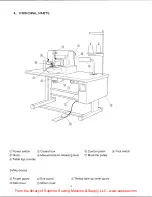
Page 4: ...LLC www supsew com 4 PRINCIPAL PARTS CD Power switch Control box Control panel Foot switch Motor Tabletop console Manual tension releasing lever 0 Machine pulley Safety device Finger guard Belt cover Eye guard Motor cover jJ Thread take up lever guard 2 ...

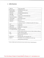
Page 5: ...es hook is used in 101 Standard hook is used in other machines Wiper Standard fitting Thread trimmer Standard fitting Bobbin counter Indicates when to change bobbin Data memorizing system EEPROM No of patterns memorized 22 patterns already input Additional patterns up to 64 max can be input Total No of stitches 10 000 max Motor 3 phase induction motor 400W Weight Machine head approximately 51 kg C...

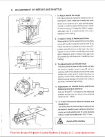
Page 6: ...le point If Catalog No 3355 01 needle is used align mark on needle bar with lower end of needle bar lower bushing 3 To Adjust Needle and Shuttle Driver Tum driving wheel by hand and align shuttle point with the center of needle Loosen screw and turn oscillating shaft bushing adjusting stud so that needle contacts with shuttle driver If shuttle driver does not properly contact needle needle and shu...

Page 7: ...ove bruises with emery cloth and polish with green rouge Switch off the machine 7 ADJUSTMENT OF OSCILLATING SHAFT GEAR BACKLASH Loosen set screw CD tum and adjust oscillating rock shaft eccentric hinge pin so that when shuttle driver is turned by hand in the rotating direction play at the end of driver is less than 0 05mm Switch off the machine 8 ADJUSTMENT OF FEED PLATE LOCATION 5 For Light Mater...

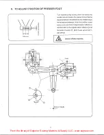
Page 8: ... into needle hole and position the presser foot so that the clearance between the presserfoot and needle is equal front to back and sideways Underthis condrtion loosen sensor screw and tum original position reflector CD until the notch on the original position reflector CD is at the center of sensor Both X axis sensor and Y axis sensor Switch off the machine 0 __ 1 1 l f p t j f b tt 6 6 ...

Page 9: ...e Then tighten screw D making sure that there is no play between lateral driving cam and roller 2 Longitudinal Driving Cam Bracket Loosen longitudinal driving cam bracket screw 2 places and push bracket in the direction shown with arrow mark parallel to the locating suriace machined suriace Then tighten screw making sure that there is no play between longitudinal driving cam and roller 0 Switch of...

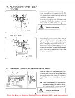
Page 10: ...that the clearance between portion A of finger guard and the needle point is 3 mm when portion A of finger guard passes the needle point Then loosen screw and move finger guard to the left or right as required so that the distance between portion A and the needle point is 20 mm when the clamp is in down position 12 TO ADJUST TENSION RELEASING BAR SOLENOID 8 Loosen set screw and adjust opening plat...

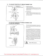
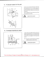
Page 11: ...dle bar connecting stud E E l J c i _ Underside of the arm 9 Thread trimming timing is adjusted by aligning timing mark on the arm shaft with the timing mark of thread trimmer cam Fora closer adjustment preform the following measure Push knife bar operating lever CD in the direction indicated by arrow at the machine upper stop position and hold it so that roller is in the groove of thread trimmer ...

Page 12: ... the thread trimmer cam D smoothly when needle bar comes down to its lowest point After the adjustment secure adjusting screw with nut so that it will not rotate Switch off the machine Loosen screw 2 places and and adjust the position of shaft so that the rear end of shaft is located 2 0mm inside from the face end of bushing CD when the roller is out of engagement with thread trimmer cam Note Be s...

Page 13: ...the knife and the center of needle hole in throat plate is 2 1 mm Clearance between for reference Size of needle hole statimary knife and Clearance between center of needle hole stationary knife and edoe of needle hole 0 1 6 2 1mm 0 6mm 0 2 0 2 1mm 0 6mm 0 2 5 2 1mm 0 3mm Adjust height of stationary knife G so it is 0 1 0 15 mm higherthan throat plate needle hole higher edge Adjust height of movab...

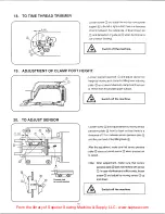
Page 14: ...d adjust clamp foot height by moving arch clamp foot lifting lever adJusting plate up or down Maximum clamp foot lift amount is 17mm from throat plate upper surface Switch off the machine Loosen screw and adjust sensor by moving sensor perceive plate front to back so that there is a clearance of 17mm between sensor perceive plate and the point end of foot lifting block After the adjustment make su...

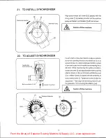
Page 15: ...ff the machine Fix arm shaft so that when machine pulley is rotated in its normal operating direction and needle bar is on its upward stroke the distance between bottom surface of arm and upper end of needle bar connecting link is 36 5mm While maintaining this setting condition loosen set screw and adjust synchronizer by turning reflector black on the synchronizer until the face end of reflector b...

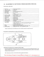
Page 16: ...3 pattern Nos 10 11 and 12 of the 25 patterns can be sewn Additional patterns up to 64 max can be input Total No of stitches 1O 000 max Motor 3 phase induction motor 400 W Weiqht Machine head aooroximatelv 51 ka Control box 11 kq Electrical ratina Sinale phase 100 115 V 3 ohase 200 240 V Maximum efficient speed is determinded upon nature of operation and type of material being sewn 2 Adjustment of...

Page 17: ... required Maximum clamp foot lift is 17mm from the throat plate surface Note Clamp toot lift is set to 12mm when the machine is shipped from the factory 1 4 Adjustment of Clamp Foot Spring Tension Loosen adjusting nut lower CD and adjust spring tension by turning adjusting nut upper The pressure on the fabric should be as light as possible while still sufficient to insure proper feeding 15 ...

Page 18: ...27 already input Max No of stitch 10 000 stitches Clamp lift system Electro maqnetic solenoid Clamp foot lift 13 mm Shuttle hook Standard hook Wiper Standard fittinq Thread trimmer Standard fittinq Bobbin counter Indicates when to chanqe bobbin Data memorizinq EEP ROM No of pattern 27 patterns already input memorized Additional patterns up to 64 max can be input Total No of stitches 10 000 max Mot...

Page 19: ... or down as required Maximum button clamp lift above throat plate surface is 13mm Loosen adjusting nut lower CD and adjust spring pressure by turning adjusting nut upper The pressure on the fabric should be as light as possible while still sufficient to insure proper feeding Loosen adjusting plate screw CD and adjust clamp spreader adjusting plate so that clearance between adjusting plate and scre...

Page 20: ...18962 standard 557131 003 standard 2 5 3 5 418973 optional 557131 003 standard 41831 0 optional 557131 001 optional 418962 standard 557131 004 optional 3 5 4 5 418973 optional 557131 004 optional 418310 optional 557131 002 optional 418962 standard 557131 005 optional 4 5 6 5 418973 optional 557131 005 optional 41831 0 optional 557131 003 standard Note Throat plate needle hole bushing PIN 418973 1 ...

Page 21: ...on of thread releaser solenoid 8 Operation of closing clamp foot solenoid 1669U200 9 Output to synchronizer and feed sensor X axis and Y axis 0 PATTERN NO Q SCALE X SCALE Y 0 0 SPEED Q 0 rg ER c 7 I fl SINGER 1669U 2 3 4 OFF 21 How to activate check mode 1 Tum main switch off 2 Press DIP switch 1 on the frond side of control box toward OFF side Off position 3 Tum main switch on The display window ...

Page 22: ...to operation Press RESIT key The sewing machine motor stops 3 To check operation of pulse motor to return to its original position Press key Ci Feed clamp mechanism will move to its original position 4 To check operation of pulse motor Press TEST key Pulse motor for X axis and Y axis feed goes into operation Both X axis and Y axis feeding take place for 30 pulses approximately 3mm at presser foot ...

Page 23: ...eration The solenoid is turned off automatically after approx 2 seconds 8 To check operation of closing clamp foot solenoid 1669U200 Press ENTER key 0 Closing clamp foot solenoid will be activated The solenoid is turned off automatically after approx 2 seconds 9 To check input to synchronizer and feed sensor 1 Press TEST key 2 The display window shows the following IB El El Ji 9 1 X axis feed sens...

Page 24: ... IEl EJ El 01 3 Needle up sensor When needle rises up to its up position by turning machine pulley by hand PATTERN NO LED lights up When the notch on the back reflector is above the sensor 4 Pulse motor timing When the notch on the red reflector is above the sensor SPEED LED lights up 5 Tachogenerator When machine pulley is turned by hand BOBBIN COUNTER LED lights up Periphery of the black reflect...

Page 25: ...ginal position 4 Operation of pulse motor 5 Operation of thread trimmer solenoid 6 Operation of presser foot lifter solenoid 7 Operation of thread releaser solenoid 8 Operation of closing clamp foot solenoid 9 Output to synchronizer and feed sensor X axis and Y axis How to activate check mode 1 Tum main switch on 2 While pressing key J press key RESET 3 The display window CD shows the following El...

Page 26: ...ress 0 P r key The sewing machine mo tor starts to rotate putting the machine into operation Press key The sewing machine motor stops 3 To check operation of pulse motor to return to its original position Only PROM Ver2 0 can be used Press C3 Jkey Feed clamp mechanism will move to its original position 4 To check operation of pulse motor Press ey Pulse motor for X axis and Y axis feed goes into op...

Page 27: ...ser solenoid Press 0 11uLP key 0 Thread releaser solenoid is turned on and goes into operation The solenoid is turned off automatically after approx 2 seconds 8 To check operation of closing clamp foot solenoid 1669U200 Press ENTER key Closing clamp foot solenoid will be activated The solenoid is turned off automatically after approx 2 seconds Press C Jkey Thread trimmer solenoid is turned on and ...

Page 28: ... G l f 1 it1 11 0 0 JJool MULP CLAMP 1 LJ SET SEL When needle rises up to its up position by turning machine pulley by hand PATT NO LED lights up When the notch on the black reflector is above the sensor 3 Pulse motor timing When the notch on the red reflector is above the sensor SPEED LED lights up 4 Tachogenerator When machine pully is turned by hand BOBBIN SET LED lights up Periphery of the bla...

Page 29: ...ter sensor has not been input X axis feed mechanism is in abnormal condition or signal for X axis feed sensor has not been input Y axis feed mechanism is in abnormal condition or signal for Y axis feed sensor has not been input 29 Corrective Measure Raise needle bar to its upper stop position by turning machine pulley With main switch off check EEP ROM for poor contact or change EEP ROM With main ...

Page 30: ...INTS 1 Feed Plate Carrier Bar Driving slide block Carrier bar stud roller Carrier bar stud 2 Knife Bar Operating Crank Shaft Inside of knife bar operating crank shaft _ 3 Knife Bar Operating Cam Knife bar operating cam 4 Arch Clamp Foot Lifting Lever Adjusting Plate Adjusting Plate 30 ...

Page 31: ...e of thread used and material being sewn 4 Needle interferes with shuttle Adjust setting of shuttle driver driver see page 4 5 Needle interferes with clamp foot Adjust setting of clamp foot see page 5 6 Wiper interferes with needle Adjust height of wiper see page 8 7 Needle interferes with movable Adjust setting of knife bar operating knife cam see page 8 and timing of knife see page 10 3 Thread b...

Page 32: ...ishing agent or replace plate needle hole bushing marred with new part 6 Improper setting and timing of Adjust setting of knife bar operating movable knife cam see page 8 and movable knife see page 10 6 Malfunction of thread trimmer 1 Knife dull Needle thread or bobbin thread cannot be trimmed when clamp 1 1 Worn stationary and movable Replace with new knives foot is in its up position at end of k...

Page 33: ...e 4 1 2 Improper feed timing Adjust synchronizer see page 12 1 3 Improper sewing speed Reduce the speed at the start of sewing slow start 2 Needle thread end too short 2 1 Improperly adjusted pre tension Adjust pre tension 2 2 Improper timing of tension Adjust timing of tension releasing bar release see page 8 2 3 Thread take up spring stroke Adjust amount of take up spring excessive stroke 2 4 Im...

Page 34: ...nge main control board Failure in motor speed output 2 Defective inverter board Change inverter board 15 E 32 or E33 appears when 1 Shield plate fastened to pulse Check fitting condition and adjust if returning to original position motor became loose required 2 Incorrect connection of sensor Check connection and rewire if C011 and C01 connected the required other way around 3 Defective feed sensor...

Page 35: ...board 18 Operation of panel not possible 1 Control panel board defective Change control panel board Defective switches 2 Defective control panel cord Change control panel cord Breakage etc 3 Defective main control board Change main control board Panel communication system failure 19 No message appears on the 1 Defective control panel board Change control pane board display Defective LED etc 2 Defe...

Page 36: ... ow V I Vl o t O u I LO CONTROL PANEL CORD 555734 FOOT SWITCH I 555772 SYNCHRONIZER D Q D 0 z w __ 0 ti W V J w 0 Z 0 z w b to I D LJ r 555721 MAIN CONTROL BOARD n 556514 PROM 556515 EEPROM n 555729 INVERTER MAIN CONTROL CORD Q 0 0 u b 0 b r i nO 1 555720 INVERTER BOARD C l 554110 RESISTOR For expon 555728 INVERTER POWER CORD L J 555726 FAN u Q _ _ _ _ _ __J 555724 C POWER SUPPLY BOARD bl l ID NU ...

Page 37: ...iN tl n 1 o n G lcnG ltllC ltll tl o tlO J o 0 nzoz zn z ___ nn u n a 0 c o i G lcn25n 0 nz o 25c N n a 1 1 1 1 m z 8 r J o CO14 l CXl z n 0 z 3 0 0 r tlJ 0 0 0 37 n 0 N tl z r co 13 vcc AFL S GNAL GND co 12 vcc X SIGNAL GND COil VCC y SIGNAL GND TG CO l OP S T SYNC N U 1 r GND vcc white 3 2 red l black red e ...

Page 38: ...m the library of Superior Sewing Machine Supply LLC www supsew com 32 D C POWER SUPPLY BOARD DIAGRAM brown red I white N blue u J h ack u J i r een 33 INVERTER BOARD DIAGRAM e I I ow I I I I I CJ CJ CD 38 ...

Reviews: