ForM 160.75-N1 (309)
33
JohNSoN CoNtroLS
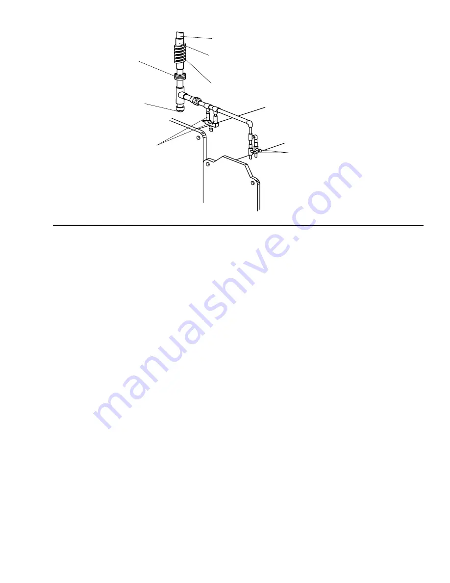
fig. 24 – tYPicial rEfrigErant VEnt PiPing
stop Valves
Stop valves may be provided (by others) in the
evaporator and condenser water piping adjacent to the
unit to facilitate maintenance. Thermometer wells and
pressure taps should be provided (by others) in the piping
as close to the unit as possible to facilitate operating
check.
flow switches
Thermal type water flow switches are factory mounted in
the chilled and condensed water nozzles and are factory
wired to the OptiView™ control panel. These solid-state
flow sensors have a small internal heating element and
use the cooling effect of the flowing fluid to sense when
an adequate flow rate has been established.
Waterbox drain and Vent Valves
Drain and vent valves (by others) should be installed
in the connections provided in the evaporator and
condenser liquid heads. These connections may be
piped to drain if desired.
checking Piping circuits and Venting air
After the water piping is completed, but before any water
box insulation is applied. Tighten and torque to maintain
between 30 and 60 ft. lbs. (41 and 81 N·m) the nuts on
the liquid head flanges. Gasket shrinkage and handling
during transit cause nuts to loosen. If water pressure is
applied before tightening is done, the gaskets may be
damaged and have to be replaced. Fill the chilled and
condenser water circuits, operate the pumps manually
and carefully check the evaporator and condenser water
heads and piping for leaks. Repair leaks as necessary.
before initial operation of the unit both water circuits
should be thoroughly vented of all air at the high
points.
rEfrigErant rEliEf PiPing
Each unit is equipped with pressure relief valves located
on the condenser and on the evaporator for the purpose
of quickly relieving excess pressure of the refrigerant
charge to the atmosphere as a safety precaution in case
of an emergency, such as fire.
Refrigerant relief vent piping (by others), from the relief
valves to the outside of the building, is required by code
in most areas and should be installed on all chillers. The
vent line should be sized in accordance with the ANSI/
ASHRAE-15, or local code.
The vent line must include
a dirt trap in the vertical leg to intercept and permit clean
out and to trap any vent stack condensation. The piping
MUST be arranged to avoid strain on the relief valves,
using a flexible connection, if necessary.
unit PiPing
Compressor lubricant piping and system external piping
are factory installed on all units shipped assembled. On
units shipped dismantled, the following piping should be
completed under the supervision of the Johnson Controls
representative: (1) the lubricant piping to oil sump and
oil evaporator and system oil return connections using
material furnished. See Form 160.75-N3.
FLANGED JoINt
to PErMIt PIPING
DISASSEMBLY
CoNDENSAtIoN
trAP
DUAL rELIEF
VALVES
VENt to AtMoSPhErE
SUPPort VENt PIPING to AVoID
StrAIN oN rELIEF PIPING
FLEXIBLE CoNNECtor
CoNDENSEr
CooLEr
SEE NotE
NotE:�ShELLS MAY BE FUrNIShED WIth
�
oNE or tWo rELIEF VALVES,
�
DEPENDING oN ShELL SIZE.
LD03863
EVAPorAtor
Summary of Contents for York MaxE YK Series
Page 2: ...Page 2 of 2 ...
Page 3: ......
Page 4: ......
Page 5: ......
Page 6: ......
Page 7: ......
Page 8: ......
Page 9: ......
Page 10: ......
Page 11: ......
Page 12: ......
Page 13: ......
Page 14: ......
Page 15: ......
Page 16: ......
Page 17: ......
Page 18: ......
Page 19: ......
Page 20: ......
Page 21: ......
Page 22: ......
Page 23: ......
Page 24: ......
Page 25: ......
Page 26: ......
Page 27: ......
Page 28: ......
Page 29: ......
Page 30: ......
Page 31: ......
Page 32: ......
Page 33: ......
Page 34: ......
Page 35: ......
Page 36: ......
Page 37: ......
Page 38: ......
Page 39: ......
Page 40: ......
Page 41: ......
Page 42: ......
Page 43: ......
Page 44: ......
Page 45: ......
Page 46: ......
Page 47: ......
Page 48: ......
Page 49: ......
Page 50: ......
Page 51: ......
Page 52: ......
Page 53: ......
Page 54: ......
Page 55: ......
Page 56: ......
Page 57: ......
Page 58: ......
Page 59: ......
Page 60: ......
Page 61: ......
Page 62: ......
Page 63: ......
Page 135: ...JOHNSON CONTROLS FORM 160 75 O1 309 36 SI metric conversion ...
Page 137: ...JOHNSON CONTROLS FORM 160 75 O1 309 38 NOTES ...
Page 138: ...FORM 160 75 O1 309 39 JOHNSON CONTROLS NOTES ...


