JohNSoN CoNtroLS
32
ForM 160.75-N1 (309)
springs are out of alignment, the misalignment must
be corrected by properly supporting the piping or by
applying heat to anneal the pipe.
If the piping is annealed to relieve
stress, the inside of the pipe must be
cleaned of scale before it is finally
bolted in place.
EVaPorator and condEnsEr WatEr PiPing
The evaporator and condenser liquid heads of chiller
have nozzles which are grooved, suitable for welding
150 PSIG
DWP flanges or the use of flexible couplings.
Factory mounted flanges are optional.
The nozzles and water pass arrangements are furnished
in accordance with the job requirements (see Product
Drawings) furnished with the job. Standard units are
designed for 150 PSIG DWP on the water side. If job
requirements are for greater than 150 PSIG DWP, check
the unit data plate before applying pressure to evaporator
or condenser to determine if the chiller has provisions
for the required DWP.
Inlet and outlet connections are identified by labels
placed adjacent to each nozzle.
chilled Water
Foreign objects which could lodge in, or block flow
through, the evaporator and condenser tubes must be
kept out of the water circuit. All water piping must be
cleaned or flushed before being connected to the chiller
pumps, or other equipment.
Permanent strainers
(supplied by others) are required
in both the evaporator and condenser water circuits to
protect the chiller as well as the pumps, tower spray
nozzles, chilled water coils and controls, etc. The
strainer must be installed in the entering chilled water
line, directly upstream of the chiller.
Water piping circuits should be arranged so that the
pumps discharge through the chiller, and should be
controlled as necessary to maintain essentially constant
chilled and condenser water flows through the unit at
all load conditions.
If pumps discharge through the chiller, the strainer may
be located upstream from pumps to protect both pump
and chiller. (Piping between strainer, pump and chiller
must be very carefully cleaned before start-up.) If pumps
are remotely installed from chiller, strainers should be
located directly upstream of the chiller.
condenser Water circuit
For proper operation of the unit, condenser refrigerant
pressure must be maintained above evaporator pressure.
If operating conditions will fulfill this requirement, no
attempt should be made to control condenser water
temperature by means of automatic valves, cycling of
the cooling tower fan or other means, since chillers are
designed to function satisfactorily and efficiently when
condenser water is allowed to seek its own temperature
level at reduced loads and off-peak seasons of the year.
However, if entering condenser water temperature can
go below the required minimum, (refer to 160.75-O1)
condenser water temperature must be maintained equal
to or slightly higher than the required minimum. Refer
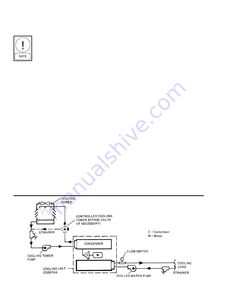
to FIG. 23 for typical water piping schematic.
fig. 23 –
SChEMAtIC oF A tYPICAL PIPING ArrANGEMENt
LD08529
EVAPorAtor
Summary of Contents for York MaxE YK Series
Page 2: ...Page 2 of 2 ...
Page 3: ......
Page 4: ......
Page 5: ......
Page 6: ......
Page 7: ......
Page 8: ......
Page 9: ......
Page 10: ......
Page 11: ......
Page 12: ......
Page 13: ......
Page 14: ......
Page 15: ......
Page 16: ......
Page 17: ......
Page 18: ......
Page 19: ......
Page 20: ......
Page 21: ......
Page 22: ......
Page 23: ......
Page 24: ......
Page 25: ......
Page 26: ......
Page 27: ......
Page 28: ......
Page 29: ......
Page 30: ......
Page 31: ......
Page 32: ......
Page 33: ......
Page 34: ......
Page 35: ......
Page 36: ......
Page 37: ......
Page 38: ......
Page 39: ......
Page 40: ......
Page 41: ......
Page 42: ......
Page 43: ......
Page 44: ......
Page 45: ......
Page 46: ......
Page 47: ......
Page 48: ......
Page 49: ......
Page 50: ......
Page 51: ......
Page 52: ......
Page 53: ......
Page 54: ......
Page 55: ......
Page 56: ......
Page 57: ......
Page 58: ......
Page 59: ......
Page 60: ......
Page 61: ......
Page 62: ......
Page 63: ......
Page 135: ...JOHNSON CONTROLS FORM 160 75 O1 309 36 SI metric conversion ...
Page 137: ...JOHNSON CONTROLS FORM 160 75 O1 309 38 NOTES ...
Page 138: ...FORM 160 75 O1 309 39 JOHNSON CONTROLS NOTES ...


