


Jetter AG
Parameterization | 8
User Manual – JXM-IO-E30
62 / 70
8.11.2 Current measurement at the PWMi_H3_X outputs
The current measurement at the PWMi_H3_X outputs is implemented via shunt resistor. The
measuring amplifier has a low-pass filter with R * C = 1 ms. This low-pass filter provides an inte-
gral component.
The arithmetic mean is measured. The CPU measures the current only midway through the turn-
on time of the PWM signal. Since there is no calculation of the ratio between turn-on time and
turn-off time, an integral component is necessary to ensure maximum reading correctness.
Usually valves already have a good average of the load current due to their self-inductance.
Purely resistive loads can be operated on the controller if the PWM frequency is set to 1 kHz.
The low-pass filter mentioned above is provided for this purpose. For lower frequencies (e.g.
100 Hz) the current measurement at purely resistive loads is too inaccurate.
8.12 Dither technology for controlling hydraulic valves
Proportional hydraulic valves are usually controlled with PWM signals of 100 Hz ... 200 Hz. The
low frequency means that the valve needle does not come to a complete stop and the control
works without major hysteresis effects.
If the valve can only be controlled at higher frequencies (1 kHz), the PWM signal can be modu-
lated. This is known as dithering and also prevents the needle from coming to rest. You can set
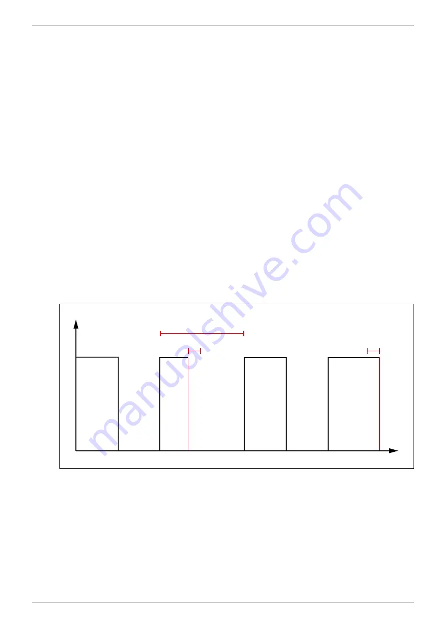
the frequency and amplitude of the dither signal in the JXM-IO-E30:
■
The dither amplitude allows you to modify the pulse length of the output signal (max. 20 %
of the period length).
■
The dither frequency allows you to set the frequency of the modification
(100 Hz ... 200 Hz).
Period 100 %
20 %
20 %
Signal
Time
Fig. 17:
Dithering