background image


Section 2: Installation

Marksman Matrix & Elite

2465-623 User Manual Rev F 

Page 2

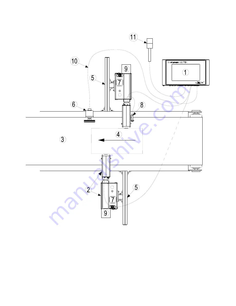
Section 2: Installation 

1 Controller, Matrix or Elite
2 Proseries Print Head
3 Conveyor
4 Product
5 Print System Bracketry
6 Encoder

7 Ink Supply
8 Photo Sensor
9 Vacuum Waste Collector Bottle
10 Encoder Cable
11 Alarm Beacon (Strobe)

Summary of Contents for Foxjet Marksman Elite

Page 1: ...Marksman MATRIX ELITE High Resolution Printing for the Real World 2465 623 Revision F User Manual 1 Missouri Research Park Drive St Charles MO 63304 Tel 800 369 5384 Illinois Tool Works Inc 2019 ...

Page 2: ...65 623 The information contained in this manual is correct and accurate at the time of its publication ITW reserves the right to change or alter any information or technical specifications at any time and without notice 2019 Illinois Tool Works Inc All rights reserved ...

Page 3: ...s unless other wise specified carries a limited warranty The inks and conditioners used with the Marksman Matrix Elite Ink Jet system carry a limited warranty For all warranty terms and conditions contact the Distributor for a complete copy of the Limited Warranty Statement ...

Page 4: ...ow 19 Configure 20 Reports 28 Delays 29 Section 6 BoxWriter Matrix Elite Editor 30 Define 30 Tools 42 Files 42 Elements 50 ToolBars 63 Perspective 65 Section 7 Maintenance and Shutdowns 66 APS Automatic Priming System 66 System Maintenance 67 Print Head Maintenance 68 Shutdown Procedures 69 Startup 69 Ink Storage 70 Section 8 Troubleshooting 71 Troubleshooting Notes 71 Troubleshooting Tests 72 Pri...

Page 5: ...art Task 88 Serial Port Modification 89 89 Printer Report Modification 89 Appendix E Hand Scanner 90 Scan and Shoot Setup 90 Scanner 90 Appendix F Communicating Directly to the Controller 92 Appendix G Using Serial cgi Commands through the Serial Port 92 Appendix H Using Marksman Net Software to Communicate to the Matrix 92 Appendix I Using the Marksman Net Protocol to Control the Matrix 92 Append...

Page 6: ...d service the equipment NOTE It is extremely important to Clean up all ink spills with the appropriate conditioners immediately and dispose of all waste according to local and state regulations Wear safety glasses and protective clothing including gloves when handling all inks and conditioners Store inks and conditioners under the recommended conditions found on the MSDS Material Safety Data Sheet...

Page 7: ...User Manual Rev F Page 2 Section 2 Installation 1 Controller Matrix or Elite 2 Proseries Print Head 3 Conveyor 4 Product 5 Print System Bracketry 6 Encoder 7 Ink Supply 8 Photo Sensor 9 Vacuum Waste Collector Bottle 10 Encoder Cable 11 Alarm Beacon Strobe ...

Page 8: ...al conveyor mounted installation Cables are not shown Materials Required for Installation You will need the following items Lint free wipes Safety goggles Level Tape measure Use appropriate safety equipment and procedures Leave print heads in their shipping car tons until all bracketry is in place and tightened down ...

Page 9: ...on and printer equipment size Assemble all bracketry to the floor conveyor or other bracketry This manual details instructions for mounting all system components to a conveyor Other mounting options for the controller and print system include the floor mount and the retract ing bracket see Appendix C Part Numbers on page 83 Assembly instructions are included with mount kits Corner brackets are att...

Page 10: ...equired to maintain a consistent throw distance See System on page 83 for bracketry options NOTE Install optional retracting bracket kit on the print head prior to mounting the print head to the conveyor bracket It may be necessary to vertically adjust each bracket s horizontal bar later to fine tune mes sage placement This is especially true when using multiple print heads as message lines will n...

Page 11: ...e right or left side of the Ink System bottom case The print head angle can be set between 0 and 90 See FJSOP4 Installation of FoxJet High Resolution AMS APS Printheads on page 97 for additional information To adjust the head to its correct angle 1 Loosen the two set screws 1 8 hex head on the print head side of the head mount 2 Rotate the head to the desired angle 3 Secure the set screws ...

Page 12: ...the print head will weep ink until the head has cooled down NOTE Ink may accumulate behind the ship cap during shipping Remove the Vent Ship Cap and Install the Fil ter Remove the Res ervoir Ship Cap and Install the Ink Bottle Remove Waste Reser voir Ship Cap and install Waste Reser voir Save caps in a zip lock bag for future use THUMBSCREWS SHIP CAP VENT SHIP CAP WASTE RESERVOIR ...

Page 13: ...sensor It emits light and detects the arrival of a product when the product reflects the light source back to the sensor The sensor then sends a signal to the controller to start the printing cycle The product detect Photosensor should be mounted on either side of the print head so that the product passes by the sensor before the print face Remove the plugs or set screws 3 32 hex head in the photo...

Page 14: ...ere it will accurately mea sure the speed of the con veyor Install it in contact with the conveyor or with a wheel or roller moving the same speed as the conveyor The encoder s mounting bracket is spring loaded Adjust the spring collar to ensure that the encoder main tains stable contact with the conveyor CAUTION Do not jam the encoder wheel against the surface of the conveyor A radial force of ov...

Page 15: ...ion Marksman Matrix Elite 2465 623 User Manual Rev F Page 10 Step 4 Electrical Cable Connections PRINT SYSTEM PRINT HEAD CABLE PHOTO SENSOR ENCODER SYSTEM PRINT ALARM BEACON STROBE MARKSMAN MATRIX OR ELITE CONTROLLER 24V ...

Page 16: ...I USB ETHERNET 12 VDC COM 1 STROBE COM 2 ENCODER 1 2 OUTPUT TO PRINTHEAD 4 3 PRINT HEAD CARDS Bottom view of Matrix Controller With Optional second PHC Board Back view of Print System Bottom view of Elite Controller HEAD 3 4 CONNECTIONS I O PORT SYSTEM CONNECTIONS POWER CORD ENCODER HEAD 1 2 CONNECTIONS ...

Page 17: ... 6 If gaps are present in the print sample follow the recommended procedure for Recircu lation as necessary until the print head passes the print quality test above 7 With all channels firing the print head is ready to begin printing Recirculation This function circulates ink through the print head to draw air out of the system It is very effective in recovering print channels 1 If not installed r...

Page 18: ...cept that it is a bit more powerful and uses a bit more ink The cycle can be started by pressing and holding the Prime Button on the rear of the print head hous ing for longer than 1 second The cycle will run while the Prime Button is held up to 5 seconds total Make sure to release the button before 10 seconds have passed to avoid entering the Recirculation mode without the Print Face Cover attach...

Page 19: ...sses the photosen sor Multiple heads can share the Auxiliary Photosensor by using the Photosensor Y Cable To change the default setting perform the following steps 1 Ensure that the rotary switch is not in the 0 position 2 Place a box in front of the photosensor 3 While the photosensor is on set the rotary switch to 0 4 When the LED stays illuminated continuously set the rotary switch to a new num...

Page 20: ...ware has an ICON user interface The main difference between the two controllers is the size and the resolution of the displays The resolutions are 1024 x 1280 for the Elite and 1024 x 600 for the Matrix The extra room on the Elite display allows for the software keyboard to be accessible at all times To access the keyboard on the Matrix simply select a field that requires keyboard input and it wil...

Page 21: ...Note User names and passwords are not case sensitive Logout Each user should log out of the Marksman Elite application after use to enforce the secu rity restrictions The user may log out by selecting the closed padlock icon from the main display The system will continue operating in its current state All menu options are dis abled after the user logs out with the exception of the Login Preview op...

Page 22: ...top message icon may be selected from the tool bar to stop the task on the selected production line Idle Message The Idle message option causes the printing to pause on the selected production line The product counts are halted until the current message is Resumed Resume Message The Resume message option causes the printing to resume on the selected production line The product counts are restored ...

Page 23: ... value Enter a 0 to print a count of 1 on the next box User Data User data or User elements may only be changed if the message is loaded The mes sage must contain user ele ments and be Running or Idle in order to modify the user data Select the User data ICON Edit the data in the lower edit box and press OK to save changes For multiple ele ments make all data changes before pressing OK to save cha...

Page 24: ...perature condition If a strobe is connected to the system this is rep resented by a flashing red light Select the icon to toggle between Info and Preview Print Head Ink level or Ink Collection bottle Green Good Yellow Low Red Out Print Head High Voltage Green Good Red Low Print Head Temperature Green Good Red Low Current Message Count Next count to be printed Production Line Print Head Status Gree...

Page 25: ... on the currently selected line will print this pattern along with the print head s name In the example below the Test Pattern is from Head 1 Configure Database Start Set a message based on data that is located in a database The database must be setup before the option is available Refer to Appendix D Database Start on page 86 Configure Print Heads Select Configure then select Print Heads from the...

Page 26: ...e desired internal encoder speed measured in feet per minute The default is 60 feet min Photosensor source Indicates whether the photosensor is external or internal The photo sensor signal from another head may also be used shared Encoder source Indicates whether the encoder is external or internal The encoder signal from another head may also be used shared Direction The direction of travel of th...

Page 27: ...ed to the Controller The data is stored under the Scan Report see Reports on page 28 No Read String The No Read String must match the No Read string that is transmit ted by a fixed scanner The printing will be stopped upon reaching the maximum value Consecutive No Reads The consecutive No Reads field is used to preform a quality check on barcodes that are printed This value determines the maximum ...

Page 28: ...8 Stop Bits Stop Bits determines the number of stop bits to be used It may be set to 1 1 5 or 2 Device Type Task Start Serial device used to select start a message generally a hand scanner Database task start Serial device used to search database for message start Barcode Verification Fixed scanner used to read each barcode after it is printed Variable Data Data to be printed imported through the ...

Page 29: ...et to zero at the start of a new message General Setting Time The main screen Time and Date field format is defined in this window There are three user controlled date and time fields that can be formatted Suppress time change warnings Used to disable software warnings of any Windows time changes Current time Windows system time General Setting Ink Codes This screen is for future enhancement ...

Page 30: ...or to configure users and access rights Add Select the Add button to create a user account Remove Select the Remove button to delete a user account Properties Select the Properties button to modify or view the user account information Firstname Enter the user s first name in this edit box Lastname Enter the user s last name in this edit box Username Enter the user s first name in this edit box ...

Page 31: ...e the screen The default access rights for each security group are shown in the following table Security Group Option Access Table Operator Manager Level 3 Graphics Dept Supervisor Level 6 Level 7 Level 8 Level 9 Administrator Output Table X Configure Print Head Settings X X X X X Start Message X X X Stop Message X X X X X Place System in Test Mode X Run Editor X Configure Production Lines X X X X...

Page 32: ...s recommended that all printing tasks be stopped until the Export function has been successfully completed To export all existing tasks choose File then Export Input the name of the file to export to or browse for an existing file by clicking the Browse button Click the Export button If the file already exists the user will be prompted to overwrite the file or cancel the request If successful a co...

Page 33: ...e information to be saved in a comma delimiter format so it can be used in other software applications Enabled Allows for the collection of data Auto Export at Task Start Exports an entry to text file defined by export path Print reports The Print Report contains historical information regarding the printing operation The print report is a table named reports within a Microsoft Access Database nam...

Page 34: ...n the location of pre printed information on the box NOTE Changes made using the Delay ICON are only temporary or until another message is started Permanent changes to the photosensor delays must be done through the Con figuration To make changes Select the desired head use the arrow buttons to decrease or increase the delay value Use the Apply button to implement the changes The incremental value...

Page 35: ...tor application The user must have the required rights to use this feature Define Boxes To define boxes select Define Boxes from the top of the Editor screen To add a new box click Add Enter the length width height and name The length width and height fields must be between 1 and 40 inches The description field is optional To edit an existing box select it and click Edit or double click the item ...

Page 36: ... it is being printed on Add Allows the operator to assign a bmp or jpg file to a panel on the box Edit Allows the operator to change which bmp or jpg file is assigned to a panel of the box Delete Will remove the file from the panel Box Usage To define box usage select Define Box usage If it is desirable to restrict a box from a given line it can be done here By default all new boxes are available ...

Page 37: ...asier to perform a resize operation on a touch screen In the example at right the eight squares around the perimeter are the resize handles Checking the Warn if elements overlap box will warn the user when element fields overlap in a message Element Defaults To define element defaults select Define Element defaults To change the defaults select an ele ment type and click Properties or double click...

Page 38: ... in pixels A value of 0 means that the sys tem will use the font s default widths Backup Path A backup of the Marksman Matrix Elite database is stored in a backup location every time the application is closed The path directs where the file is saved Custom Date Time Formats To define date time set tings select Define Cus tom date time formats The date time settings shown here are used by Date time...

Page 39: ...ck Edit or double click it The Build date time format dialog is shown below Format string Contains a user defined string consisting of format specifiers Sample Shows a sample of the current Format string Valid format specifiers are listed at the bottom of the dialog To insert them in the current string select them and click Insert or double click ...

Page 40: ... and save changes or Cancel to exit without saving changes Months Months represents the string values that are used in date codes for the standard months of the year Hours The Hours table stores the twenty four codes for the hours of the day The codes may be custom ized for special coding Quarter Hours The Quarter Hours table stores codes for 15 minute intervals Days The day table holds the value ...

Page 41: ...o define shift codes select Define Shift codes Shift codes are used by Shift ele ments The shift code s length must be from 1 to 15 characters The code s times must be in order from least to greatest i e code 1 cannot be later than code 2 or 3 Line This determines the pro duction line for the shift code definitions Select the appropriate production line Enter the shift start times and any user def...

Page 42: ...barcodes see Global Barcode Parameters on page 40 for usage The Sub elements dialog is shown below To create a new sub element click the button To delete an existing sub element select it and click the X button To edit an existing sub element select it and click the Properties button the bottom left most button The Sub element properties dialog is shown below ID Identifies the sub element ...

Page 43: ...ription of the sub element Data Contains the default data for the sub element Note that the Data must satisfy the Input mask The Input mask defines what kind of data the sub element can accept To change it click the Build button The Build mask dialog is shown at right In this example the mask is set up for data consisting of two digits and up to 10 alpha numeric characters The buttons along the ri...

Page 44: ...to 9 Punctuation allows characters such as or Any allows any character Application Identifiers To define fonts select Define Application identifiers Application identifiers can also be used by certain bar codes They work in the same manner as sub ele ments An example of the Application identi fier properties dia log is shown at right Only the Element type and Data fields can be changed See Sub Ele...

Page 45: ...dit or double click the item NOTES Only the custom bar and space parame ters can be changed and only a person having advanced knowledge of barcode and inkjet printing systems should change these parameters An unusable barcode may be printed using improper settings C128 C39 C93 I 2of5 On standard barcode parameters the Magnification Width Total height and Ratio cannot be changed Only custom paramet...

Page 46: ...he font in pixels Avg font width Defines the aver age character width in pixels A value of 0 means that Windows will use the font s default widths Magnification The value dis played in the Magnification field on the Barcode element dialog Total height The total height of the symbol in pixels Horz bearer Specifies the width of the symbol s horizontal bearer in thousandths of an inch Vert bearer Spe...

Page 47: ...t and how many prints you will get from each bottle Files New To create a new task choose File New The user will be presented with the dialog at right Pick which production line the task is to be created for give it a name and description if desired and select the box it will be printed on The Task name field must contain only letters and num bers no spaces or special characters are allowed The ma...

Page 48: ...physical devices installed Different panels can be selected to add elements to the task Once a head has been chosen select an element to be placed on the box The process is repeated until all the desired information needed on all sides of the box are completed The next step would be to save the task Refer to appropriate sections in this manual relating to Elements on page 50 and Save As on page 48...

Page 49: ...ow preview box will show a preview of the selected task For large tasks it may take several seconds to generate the pre view Copy To copy tasks from one line to another choose File Copy Select the line to copy from then select the tasks to be copied Checking the All box will auto matically select all existing tasks for the given line When the desired tasks are selected click Copy If successful you...

Page 50: ...figu rations However if they do not the user may elect to configure the head mapping To do this select the head to be mapped and click Edit or double click The user will be presented with the dialog at right Select the head to map to in the To field and click OK Clicking Properties will bring up the Head proper ties dialog Note that head properties are read only in the Editor ...

Page 51: ... database be exported for backup pur poses To import all tasks that were pre viously exported choose File then Import In the filename field input the name of the file full path the exported tasks were saved to or browse for the file by clicking the Browse button If there is data on the controller that the user does not want to lose click Yes on the follow ing screen The screen at right will appear...

Page 52: ...lready exists the user will be prompted to overwrite the file or cancel the request If successful a confirmation message will appear Delete To delete existing tasks choose File Delete Select the task to be deleted Multiple tasks may be selected by using the control and or shift keys When the selection has been made click Delete The delete function may be used several times without closing the wind...

Page 53: ...etters and numbers no spaces or special characters are allowed The maximum number of characters is 32 If the name entered matches a task already in the database the user will be prompted with a confir mation dialog like the one at right Properties To change an open task s properties choose File Properties The task s description download string box and or expiration data may be changed using this d...

Page 54: ... NULL Null SOH Start of heading STX Start of text ETX End of text EOT End of transmission ENQ Enquiry ACK Acknowledge BEL Bell BS Backspace HT Horizontal tab LF NL Line feed New line VT Vertical tab FF NP Form feed New page CR Carriage return SO Shift out SI Shift in SLE DC1 Device control 1 DC2 Device control 2 DC3 Device control 3 DC4 Device control 4 NAK Negative acknowledge SYN Synchronous idl...

Page 55: ...erial Shape New elements can be created by clicking one of the buttons on the element bar by right clicking on the printable area of the box or by using the Elements Add menu When creating a new element its x y position top left corner is set to the current location of the crosshairs To edit an existing element s properties select the element by clicking it then choose Ele ments Edit from the menu...

Page 56: ... the next line where text can also be entered Average width defines the average character width in pixels A value of 0 means that Windows will use the font s default widths The Text field displays the data to be printed This field can contain between 1 and 255 characters The Orientation field determines if the data is printed horizontally or vertically Link to Allows the user to tie a text element...

Page 57: ...ap element properties dialog is shown at right The Filename field displays the full path and filename of the selected bitmap To select a different bitmap click the Browse button To edit the selected bitmap using the default bitmap editor click Edit Note that the BoxWriter Editor will be dis abled until the bitmap editor is closed To change the default bitmap editor see Bitmap Settings on page 36 o...

Page 58: ...l counts throughout the particular message and will lock out the other count settings during the start of the task Start value Displays the starting value of the counter Roll over on Determines when the counter rolls back to the Start value The maximum number of digits for this field is six Increment by The number of units added to the current count when a photosensor event is fired Number of digi...

Page 59: ...t would increment Rollover Will reset the Pallet count to the Start value when the Maximum value is reached If unchecked the Maximum value will be as high as the Pallet count will go Date Time Element The Date time element properties dialog is shown at right Avg font width Defines the average character width in pixels A value of 0 means that Win dows will use the font s default widths Format Deter...

Page 60: ...t click the Build button For a description of the Build date time format dialog see Custom Date Time Formats on page 33 The expiration period is determined by adding the Days and HH MM SS fields to the current system time Round to top of unit Forces the expiration code that is printed to round up to the next whole unit Orientation Determines if the data is printed horizontally or vertically See Te...

Page 61: ...t When checked the operator will be prompted by the Marksman Matrix Elite Control application when the task is started The data displayed in this prompt is determined by the Prompt field Orientation Determines if the data is printed horizontally or vertically See Text on page 51 for examples of horizontal and vertical text Shift Code The Shift element properties dialog is shown at right A Shift el...

Page 62: ... be printed The following symbologies are sup ported 128 39 Standard 93 Datamatrix ECC200 GS1 DataMatrix GS1 128 GTIN 12 UPC A GTIN 13 EAN 13 GTIN 14 ITF 14 GTIN 8 EAN 8 I 2of5 QR Code UPC E Magnification Indicates when set of barcode parameters are used to draw the barcode See Global Barcode Parameters on page 40 for information on barcode parameters Data Contains the data to be encoded in the ba...

Page 63: ...nts and application identifiers To modify these uncheck the Simple data box The following is an example of a Code 128 barcode with two sub elements See the Sub Elements on page 37 and Application Identifiers on page 39 for more infor mation Move item up or down in list Properties Insert Application Identifier Insert new sub element ...

Page 64: ...the Select Data Source dialog see next page Table Displays the table in the database to query Field Displays the field name in the selected table The value of this field is data that will be printed The user may also browse the fields in the current table by clicking Select see the Select field dialog on the next page If a given record is to be retrieved by a key value check the Use box under Key ...

Page 65: ...Section 6 BoxWriter Matrix Elite Editor Marksman Matrix Elite 2465 623 User Manual Rev F Page 60 Following is an example of what the Select Data Source dialog might look like ...

Page 66: ...owing is an example of what the Select field dialog might look like To insert an SQL statement directly click the General statement tab An example using a general SQL state ment is shown at right If this option is used the first field in the first record of the result set will be the data selected to print ...

Page 67: ...r width in pixels A value of 0 means that Windows will use the font s default widths Start index Specifies the index in the serial buffer to start copying from Length Specifies how many characters to copy from the serial buffer Orientation Determines if the data is printed horizontally or vertically See the Text Element section for examples of horizontal and vertical text In the Editor a Serial el...

Page 68: ...200 About This command displays the About dialog This dialog lists all the major components of the editor and their version numbers Font bar The font bar allows the user to change the font properties of any selected elements that have a font i e Text Count and Date time elements New Task Open Task Save Current Task Delete Copy Selected Element Undo Cut Selected Element Paste Zoom In Redo Zoom Out ...

Page 69: ...positioned Otherwise click No and the box will be returned to its original orientation Alignment Bar The alignment bar allows the user to apply various transformations to the currently selected elements NOTE The minimum number of elements that must be selected for Left Center Right Top Middle and Bottom is two 2 The minimum number of elements that must be selected for Distribute evenly vertically ...

Page 70: ...trix Elite Editor Marksman Matrix Elite 2465 623 User Manual Rev F Page 65 Perspective To change the perspective of the box view select View Change perspective The x and y axis perspectives must be between 90 and 90 degrees ...

Page 71: ...ndi cation Low ink indication is caused by either low ink in the reservoir or full ink in the waste collection bottle The APS is an invaluable tool for routine cleaning of loose debris from the print engine face The images below demonstrate print before and after the APS See FJSOP2 Daily Maintenance for AMS APS Printheads on page 95 for additional information NOTE The duration of the APS cycle is ...

Page 72: ... might have collected on the print head faceplate see Step 5 Priming the Print Heads on page 12 Inspect for broken or worn electrical connections Inspect guide box rails and print head bracket for wear Make sure the controller cabinet fan s are working and that they turn freely Have a qualified technician open the printer cabinet and inspect for dust If necessary blow out dust with low pressure ai...

Page 73: ...d wiping the front plate and enclosure If debris build up is noted on the enclosure and rear of the print head then wipe those clean too NOTE DO NOT SPRAY N PROPANOL MAINTENANCE SPRAY DIRECTLY ON THE PRINT HEAD OR ANYWHERE NEAR THE ORIFICE PLATE Using a sponge swab 5760 832 rub the orifice plate lightly from top down in a vertical direction while ink is flowing during an APS Automatic Prim ing Sys...

Page 74: ...rvoir vent cap and install the reservoir ship cap Install the ship cap onto the front of the print head Shutdowns of 3 Months or More Follow recommendations for Shutdowns of 1 Week to 3 Months above It is recommended that the print head system be flushed with ScanTrue II Flush Solu tion and that ScanTrue II Flush Solution be left in the print head during the storage period See Appendix C Part Numb...

Page 75: ...90 relative humidity with no condensa tion Temperatures above or below the recommended storage temperature for a period greater than one week will reduce the storage life of the ink NOTE Do not shake the bottle of ink before use Agitating the ink may introduce air into the Print Head If shaken the bottle must sit for at least two hours before use Use Life of an OPENED Bottle of Ink ScanTrue II 3 m...

Page 76: ...er and photosensor See Appendix B Theory of Operation for details Problem Cannot communicate to the Marksman Matrix or Elite through the Ether net Action Power down then power up the computer and the Controller Check for proper Ethernet cabling Verify that the IP addresses are valid for the computer and the Controller Problem The system does not print Action Check that there are no errors on the h...

Page 77: ...e operation Photosensor Sensitivity Test This test will determine if the photosensor sensitivity is adjusted correctly for the applica tion NOTE The test object should be a sample of the actual product 1 Place the test object approximately inch in front of photosensor photosensor should sense object 2 Place the test object near the center of the guide rails photosensor should sense object 3 Place ...

Page 78: ...bris on front plate air in channel Action Run APS Add brushes and positive air flow to minimize debris build up Problem Missing channels and channel fractures in print channels Possible Cause Excessive debris on front plate air in channel Action Wipe front plate and run APS Add brushes and positive air flow to minimize debris build up Problem Missing print channels Possible Cause Air in channel Ac...

Page 79: ...on Wipe front plate and run APS Problem Fuzzy print Possible Cause Print head too far away from substrate Action Move print head to within 1 8 from product Problem Occasional checkerboard print pattern Possible Cause Encoder slipping or bouncing on belt Action Tighten encoder on belt replace encoder o rings if required or replace conveyor belt with a smooth seamless belt ...

Page 80: ...se Incorrect encoder or incorrect line speed set too low if using internal encoder Action Check for correct encoder use 5000 PPR Encoder Problem Short image dark print checkerboard pattern Possible Cause Incorrect encoder or wheel size or incorrect line speed set too high if using internal encoder Action Check for correct encoder use 5000 PPR Encoder ...

Page 81: ... GB Solid State SATA drive Alarm Optional 3 color LED beacon Enclosure Stainless Steel Weight 8 13lb Controller only Operation System Windows Embedded Standard 7 32 Bit Display 10 2 inch 1024 x 600 LCD with Resistive touch screen Keypad Software Electrical 90 240 VAC 50 60Hz 2 0A max power supply input 2 each 24 VDC 5 0A Controller input Environment Ambient operating temperature 40 to 104 F 5 to 4...

Page 82: ...2 J1 PHC BOARD 2 JUMPER SETTINGS ON 2465 630 2465 331 2465 323 2465 621 2465 629 2465 612 2465 615 2465 616 2465 628 DISPLAY DRIVER BOARD DISPLAY BRACKET AND DISPLAY STROBE FAN POWER VGA COM 2 PHC BOARD 2 PHC BOARD 1 Black Blue Black Green 2465 328 RED WIRE THIS END OFF SW SETTINGS HARD DRIVE CPU JUMPER SETTINGS ...

Page 83: ... 204pin DDR3L SO DIMM Data Storage 128 GB Solid State SATA drive Alarm Optional 3 color beacon Enclosure Stainless Steel Weight 26 5 lbs 12 0 kg Controller only Operation System Windows Embedded Standard 7 Display 17 diagonal 1280x1024 LCD with Resistive touch screen Keypad Software Environment Ambient operating temperature 40 to 104 F 5 to 40 C Operating humidity 10 90 non condensing Print head t...

Page 84: ...N 2465 329 AC PWR 12V 24V PWR SUPPLY P N 2465 348 CABLE USB PHC TO CPU P N 2465 323 CPU PHC BOARD USB CONNECTOR CPU BOARD USB DISPLAY ATX12V POWER SUPPLY 24V CAPACITOR POWER SUPPLY 12V HARD DRIVE CABLE 24V PWR SUPPLY TO PHC BOARD P N 2465 322 FAN FAN 12V PWR TO CPU DIPSLAY P N 2465 345 CABLE USB CPU TO DISPLAY P N 2465 330 USB POWER SATA SATA BLUE POWER CORD REMOVE JUMPER FROM J1 ON SECOND TOP PHC...

Page 85: ... 25 6mm 14 31in 363 5mm 5 00in 127 0mm 2 75in 69 9mm 3 02in 76 7mm 5 50in 139 7mm 12 60in 320 1mm 21 32in 541 5mm 11 70in 297 1mm 3 00in 76 2mm 2X 10 32 X 25 DEEP BOTH SIDES 2X 10 32 X 25 DEEP BOTH SIDES 21 77in 552 9mm 3 00in 76 2mm 13 05in 331 5mm 11 70in 297 1mm 2 80in 71 1mm 6 32in 160 5mm 14 31in 363 5mm 5 50 139 7 3 02in 76 7mm 1 07in 27 2mm ...

Page 86: ...loat switch sensor Low ink and full waste bottle detection waste detection not included with AlphaCoder Print Heads Ink Specifications ScanTrue II PLUS 384e and 768e Print Heads Pigmented oil based for porous surfaces Technical Data Operating Conditions Temperature 50 104 F 10 40 C Relative Humidity 20 80 non condensing Storage Conditions Temperature 32 109 F 0 43 C Relative Humidity 20 80 non con...

Page 87: ... supply Print Heads The Marksman Matrix Elite supports all the Marksman series printheads A typical prin thead includes a reservoir section drive electronics and a print engine The information and power needed for printing are sent to the print head through the DB25 The drive electronics include a Universal Driver Board and Marksman Driver Board The Universal Board takes 24VDC and generates the hi...

Page 88: ...omestic 2465004E2 Marksman Elite 2 Head European Print Head Controller Bracketry 2464550 Print Head Conveyor Mount Bracket 2464561 X Y Axis Linear Adjustment Tool LessBracket 2464562 Conveyor Mount Roller Bracket for 768 Print Head 2464563 Print Head Floor Mount Bracket Kit 2464564 Conveyor Mount Roller Bracket for 384 Print Head 2465243 Kit T Stand Matrix Elite 2465244 Kit Conveyor Mounting Matri...

Page 89: ...acement 6000171 Print Head Wiping Cloth 300 pack Part Number Description 2465266 Kit Display 2465246 Kit Print Head Controller Board upgrade replacement 2465268 Kit 24V to 12V Board 2465278 Kit CPU Board and Hard Drive Matrix 5760333 Kit Power Supply 24V Part Number Description 2465245 Kit Display 2465246 Kit Print Head Controller Board upgrade replacement 2465260 Kit CPU Board Windows 7 2465277 K...

Page 90: ...2464616 Reservoir Ink Line Tubing Replacement Kit ScanTrue II PLUS 4 2464617 APS PCB Replacement Kit 5 2464618 Ink Separator Replacement Kit 6 2464620 Ink Waste Bottle Kit ScanTrue II PLUS Ink 4 pack 7 2464649 Vent Filter Replacement Kit 9 2464414 Cable DB 25 Connector to HV Board 10 2464144 Cable Driver Board to APS PCB 11 5760527 Cable Reservoir to APS PCB 12 2464146 Cable Prime Pump to APS PCB ...

Page 91: ...by using the Start play button on the tool bar Instead of see ing the Start Message screen a new Start Task screen will open If the Other button is used the Database Task Start option is bypassed and the normal Start Message screen appears Standard or Database mes sages can be started as normal 2 The system will respond by prompting the user for a key field value 3 Based on the user s input the so...

Page 92: ...e this data will reside the details must be entered on the new menu option Configure Database start First click the Select button to select the DSN entry to use when utilizing the database start routine Each of the available tables or sheets will be available based on the DSN entry Select the appropriate table for use Next choose the field that will be utilized for the Key field to identify the re...

Page 93: ...ey Field column to the desired data and press OK This will return you to the Start task Press OK to start the process Serial Port Modification In addition to accessing the new menu option and toolbar button the serial port options have been modified to allow for a Database task start as seen in the figure at right When set to the database task start setting the system will accept serial input from...

Page 94: ...ual Rev F Page 89 Printer Report Modification In order to determine what key field has been selected by the operator the printer report has been modified to indicate the chosen key field The key field will be indicated on the preceding line under the Task Name field ...

Page 95: ...creat ing a task and giving it the name of the 5 digits of the barcode being used to start the task In the example below the barcode being scanned is 0 79068 17001 7 The part of the barcode that will be used to identify the task is highlighted 17001 This is the name that will be given to the task A task should now be created using the name 17001 Scanner Plug the scanner into a serial port either t...

Page 96: ...troller should now be set up to start a task using a hand scanner Make sure there are no tasks running use the Stop button if a task is selected Use the hand scanner and scan the barcode that the task was created from If the task starts then the controller is set up Additional tasks can now be added as needed using the same approach as above If the task fails to start Check that the scanner is pro...

Page 97: ...ndix G Using Serial cgi Commands through the Serial Port Refer to the Marksman Duo Serial Commands document 2465654N Appendix H Using Marksman Net Software to Communicate to the Matrix Refer to the Marksman Net Marksman Next manual 2464308 Appendix I Using the Marksman Net Protocol to Control the Matrix Refer to the Marksman Net Commands document 2465655N Appendix J Using the Print Monitor Softwar...

Page 98: ...line PROCEDURE 1 Initiate the proper controller shutdown procedure TURN OFF AND UNPLUG THE CONTROLLER from electrical power source to avoid possible electrical problems and or electric shock 2 Disconnect all printhead cables from the controller 3 Remove the ink bottle and install the Res ervoir Ship Cap 4 Remove vent cap filter if applicable and close the vent cap 5 For an AMS APS system remove Wa...

Page 99: ...ly and secure it with tape 12 If the printhead is to be stored for later use it should be stored in a cool dry location 13 If the printhead is to be shipped it should be well padded and packed in its original shipping box CAUTION Observance and practice of this procedure is critical to insure no damage occurs during shipping FoxJet will replace and charge for any items found to be missing before i...

Page 100: ...he center slot that protects the CP OP nozzles Failure to wipe in the appropriate direction may cause blockage in the CP OP 2 Press and release the Purge button to initiate an automatic prime purge cycle observe that the ink is vacuumed off the CP OP 3 If necessary wipe excess ink from the bottom of the faceplate with a lint free cloth If ink continues to drip onto the faceplate when the Purge but...

Page 101: ...any channels that still do not print repeat steps 8 through 12 as required Replacing APS waste ink bottles FoxJet APS systems have waste ink catch bottles installed to the rear of the printhead ink system and employ a waste ink detection circuit to disengage the APS feature when the bot tle becomes full Failure to replace a full waste ink bottle will disengage the APS system To maximize equipment ...

Page 102: ...0 25 away from the side of the carton as it passes in front of the printhead 5 Insure that conveyor guides are adjusted so that the cartons CANNOT hit the print head 6 Remove the Reservoir ship cap and install the ink bottle insure the expiration date on the ink bottle has not yet occurred 7 Open the vent cap and install a clean vent cap filter FoxJet PN 5765210 8 Remove and the save the APS bottl...

Page 103: ... step until no bubbles are present in the ink flow If there are still bubbles after ten attempts contact your FoxJet Service Representative 19 Run a print sample to ensure all the channels are printing and producing good print quality IF PRINT QUALITY IS ACCEPTABLE PROCEED NO FURTHER 20 If there are voids horizontal lines in the print allow the Printhead to heat for four hours If the Printhead is ...

Reviews: