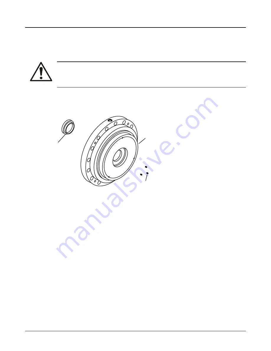
a) Thoroughly clean the bushing fit in the seal-chamber cover.
b) Chill the new bushing using dry ice or another suitable chilling substance, and install the bush-
ing into the cover fit.
Tap the bushing in place with a wood block or soft-faced hammer.
WARNING:
Dry ice and other chilling substances can cause physical injury. Contact the supplier for infor-
mation and advice for proper handling precautions and procedures.
c)
Locate, drill, and tap three new equally-spaced set screw holes on the impeller side of the cov-
er between the original set screw holes.
d) Install the set screws and upset threads.
1
2
3
1.
Seal-chamber cover
2.
Set screws
3.
Bushing
Figure 63: Set screw installation
6.5.7 Bearing-frame inspection
Checklist
Check the bearing frame for these conditions:
•
Visually inspect the bearing frame and frame foot for cracks.
•
Check the inside surfaces of the frame for rust, scale, or debris. Remove all loose and foreign ma-
terial.
•
Make sure that all lubrication passages are clear.
•
Inspect the inboard-bearing bores.
If any bores are outside the measurements in the Bearing fits and tolerances table, replace the
bearing frame.
6.5 Preassembly inspections
90
Model 3700, 3703, 3710, 3700LF, 3700LFI API Type OH2 / ISO 13709 1st and 2nd Ed. / API 610 8/9/10/11th Ed. Instal-
lation, Operation, and Maintenance Manual
Summary of Contents for Goulds Pumps 3700
Page 2: ......


