User Guide
32
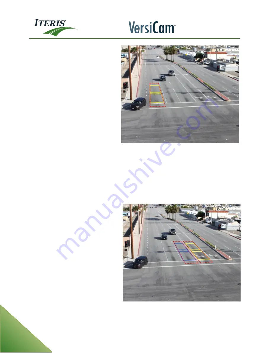
This figure is an example of the Lane Zone
Structure. Detection zones are drawn in
yellow. The lane zone structure created by
the system is shown in red.
Important:
In certain intersection control applications only certain lanes may be needed for traffic
control, left turn only for example. In these situations a lane structure should be created in the
nearest through lane. This though lane will help the algorithm determine the difference between a
vehicle and a shadow (from a vehicle in the though lane).it must still be drawn to create the lane
structure. Again the zones in the through lane should have a valid detector output, for example
Proc:1 and the zone type should be set to none.
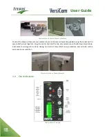
This is an example of the Lane Zone
Structure when only the left turn detection
is required. The zones drawn in yellow are
required for intersection control. The zones
drawn in blue are to aid performance and
should be zone type None and have a valid
detector output.
Summary of Contents for VersiCam
Page 1: ...Part Number 493432201 Rev F ...
Page 13: ...User Guide 13 2 1 Menu Tree ...
Page 30: ...User Guide 30 ...
Page 77: ...User Guide 77 10 TECHNICAL INFORMATION IMSA 39 2 40 2 Cable ...
Page 79: ...User Guide 79 VersiCam Specification Sheet ...
Page 80: ...User Guide 80 Phase Information ...
Page 81: ...User Guide 81 Detector Rack Configurations ...
Page 83: ...User Guide 83 ...
Page 84: ...1700 Carnegie Avenue Santa Ana CA 92705 Phone 949 270 9400 Fax 949 270 9401 ...


