


U-MATCH AIR CONDITIONERS MAINTENANCE
125
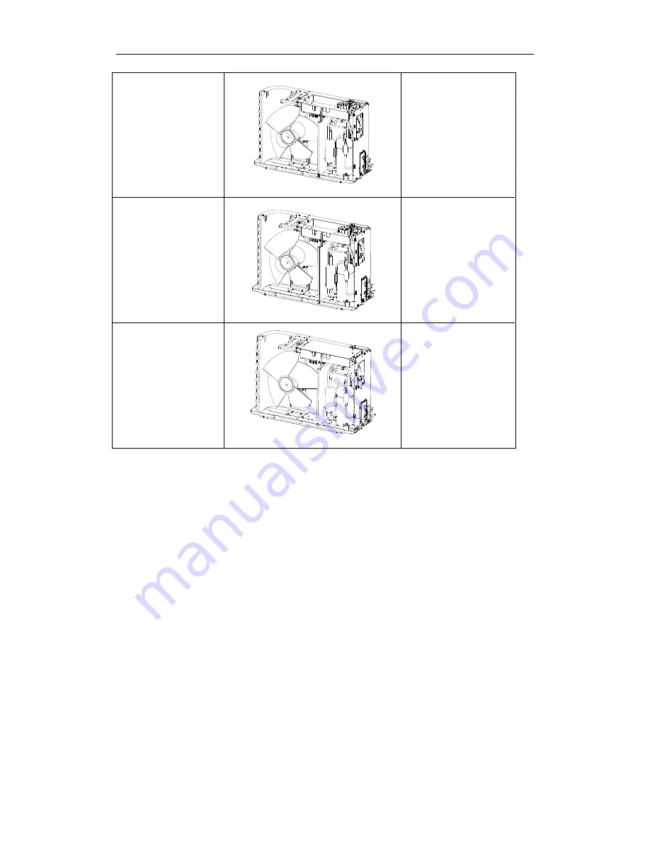
5. Assembly of new
electrical parts box
modules
Position accurately the
new electrical parts box.
Re-fasten the electrical
parts box modules and
screw down with
screwdriver.
6. Connection of power
supply wires of each
component
Re-connect the connection
wires of each components
with right position
according to the order of
disassembly.
7. Assembly of electrical
parts box
Assembly accurately the
electrical parts box.
Re-fasten and screw down
the surrounding fixing screw
with screwdriver.
Summary of Contents for u-match on/off
Page 1: ......
Page 4: ...INVENTOR COMMERCIAL AIR CONDITION U MATCH AIR CONDITIONERS 1 PRODUCT...
Page 24: ...U MATCH AIR CONDITIONERS PRODUCT 21 5 PIPING DIAGRAM...
Page 25: ...INVENTOR COMMERCIAL AIR CONDITION U MATCH AIR CONDITIONERS 22 CONTROL...
Page 26: ...U MATCH AIR CONDITIONERS CONTROL 23 CONTROL 1 OPERATION FLOWCHART 1 1 Cooling Dry Operation...
Page 27: ...U MATCH AIR CONDITIONERS CONTROL 24 1 2 Heating Operation...
Page 45: ...U MATCH AIR CONDITIONERS CONTROL 42 5 2 4 Dimensions...
Page 48: ...INVENTOR COMMERCIAL AIR CONDITION U MATCH AIR CONDITIONERS 45 INSTALLATION...
Page 91: ...INVENTOR COMMERCIAL AIR CONDITION U MATCH AIR CONDITIONERS 88 MAINTENANCE...
Page 101: ...U MATCH AIR CONDITIONERS MAINTENANCE 98 Malfunction display E6 Communications Failure...
Page 115: ...U MATCH AIR CONDITIONERS MAINTENANCE 112...
Page 163: ......


