Sabre 1555 RFID and Bar Code Reader Service Manual
2-26
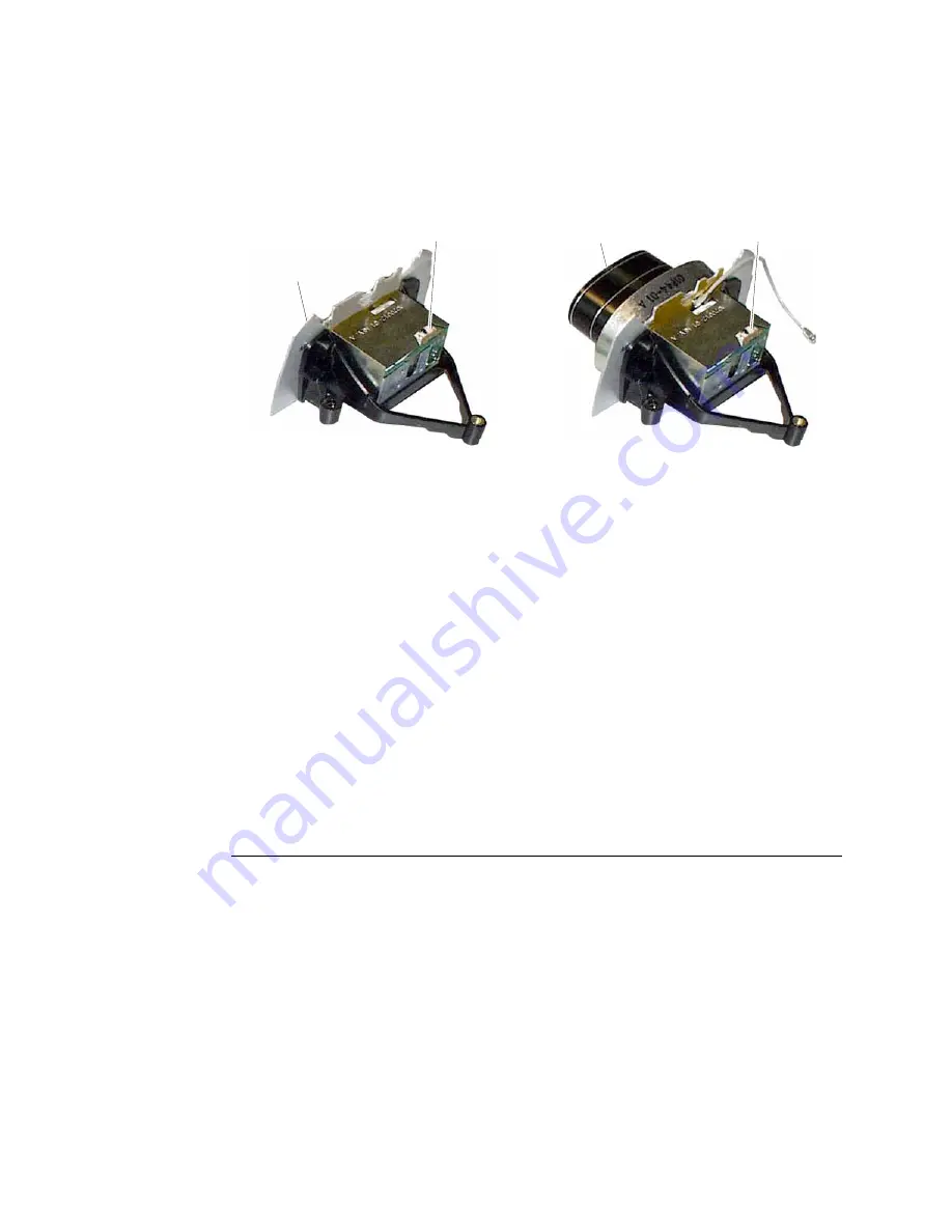
Make sure the scan engine connector faces away from the shield or antenna.
Shield and chassis assembly
Scan engine connector
Shield
Antenna
assembly
Scan engine connector
Antenna
8. Install the two Phillips screws to hold the scan engine in place. Torque to 0.339 Nm
(3.0 lb-in).
9. Slide the shield and chassis assembly or antenna assembly into position between the
digital board and the RF board. From the bottom of the RF board, install the two
Torx screws to hold the assembly onto the RF board. Torque to 0.339 Nm (3.0 lb-
in).
10. Install the Torx screw on top to hold the digital board in place on the RF board
assembly. Torque to 0.339 Nm (3.0 lb-in).
11. For a 2.4 GHz 1555, plug the antenna cable into the connector on the RF board.
12. Make sure the 8-pin connector on the back of the scan engine and the 12-pin
connector on the digital board are unlatched.
The RF board assembly is ready for installation in the lower shell. For help, see
“Reassembling the 1555” on page 2-30.
Removing and Replacing the Lower Shell
To replace the lower shell, you need:
•
Lower shell (P/N S620-CAS-002-E)
You need these tools:
•
Torque driver with a Torx bit
•
Phillips screwdriver (for PDT 1555)
Summary of Contents for Sabre 1555 RFID
Page 1: ...Sabre 1555 RFID and Bar Code Reader Service Manual...
Page 8: ...alexdaddy...
Page 9: ...Troubleshooting the 1555 1...
Page 10: ...alexdaddy...
Page 15: ...Replacing Parts in the 1555 2...
Page 16: ...alexdaddy...
Page 49: ...Testing the 1555 3...
Page 50: ...alexdaddy...
Page 60: ...alexdaddy...
Page 61: ...Exploded View and Spare Parts List 4...
Page 62: ...alexdaddy...


