1000BASE-T/100BASE-TX/10BASE-T Physical Layer Compliance Tests Manual
Intel Confidential
129
Troubleshooting Guide
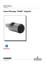
Figure G-4. Reducing jitter by reducing noise under the network controller.
Poor common mode rejection can be caused by asymmetric traces. They should be the same length,
and should run parallel to each other from end to end.
Jitter can also be caused by a crystal or oscillator that is not producing the required output
frequency.
G.11
Differential Input Signals (ANSI specification 9.2.1)
Bit error rate testing provides some of the most important test data. It is the data that can be most
readily seen by customers. If the board is incapable of receiving without large numbers of errors, it
will result in poor network performance.
Poor performance on this test can be caused by receiver circuit asymmetry or poor impedance
matching as well as failure on any of the other tests in this document. Make sure that the
transmitting unit is a known good unit. For example, don’t use two systems with new designs to
perform Bit Error tests, since any problems with the transmitter on one unit will cause the receiver
to have high BER.
G.12
Receiver Common Mode Rejection (ANSI
specification 9.2.3)
Common mode noise is noise which affects both wires in the differential pair simultaneously and in
phase. Because it is the same across the pair, it can be rejected by the receive unit. The TP-PMD
spec defines that the receiver should be able to withstand a 1 V peak-to-peak sine wave with
frequencies between 0 – 125 MHz. This simulates common mode noise that could be picked up
from running cables near power or telephony wiring.
For systems failing to meet common mode rejection specifications, verify that the common mode
choke functionality of the magnetics module has been properly implemented. Make sure the
ground planes and power planes under the magnetics module are separated by at least one-tenth of
an inch between the PHY side of the magnetics module and the chassis side. Usually, this prevents
common mode noise from bypassing the common mode chokes that are internal to the magnetics
module.
Verify the following for both of the differential pairs (TDP and TDN, RDP and RDN) from the
PHY to the magnetics module: