WAFER-8523 User Manual
Page 39
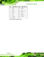
PIN Description PIN Description PIN Description PIN Description
C1
GND
C11 -MEMW
D1
GND
D11 -DACK5
C2
-SBHE
C12 SD8
D2
-MEMCS16
D12 DRQ5
C3
SA23
C13 SD9
D3
-IOCS16
D13 -DACK6
C4
SA22
C14 SD10
D4
IRQ10
D14 DRQ6
C5
SA21
C15 SD11
D5
IRQ11
D15 -DACK7
C6
SA20
C16 SD12
D6
IRQ12
D16 DRQ7
C7
SA19
C17 SD13
D7
IRQ15
D17 VCC
C8
SA18
C18 SD14
D8
IRQ14
D18 -MASTER
C9
SA17
C19 SD15
D9
-DACK0
D19 GND
C10 -MEMR
C20 NC
D10 DRQ0
D20 GND
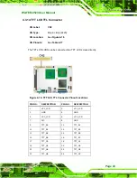
Table 4-12: PC/104 Connector Pinouts (2 of 2)
4.3.10 PC/104 Power Input Connector
CN Label:
CN8
CN Type:
3-pin wafer (1x3)
CN Location:
See
Figure 4-12
CN Pinouts:
See
Table 4-13
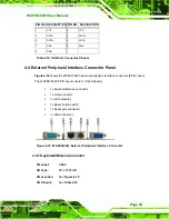
The PC/104 power input connector provides power to the PC/104 expansion module
installed on the PC/104 slot.
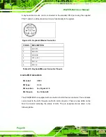
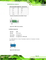
Figure 4-12: PC/104 Power Input Connector Pinouts
Summary of Contents for WAFER-8523
Page 16: ...WAFER 8523 User Manual Page 1 Chapter 1 1 Introduction...
Page 22: ...WAFER 8523 User Manual Page 7 Chapter 2 2 Detailed Specifications...
Page 36: ...WAFER 8523 User Manual Page 21 Chapter 3 3 Unpacking...
Page 40: ...WAFER 8523 User Manual Page 25 Chapter 4 4 Connectors...
Page 66: ...WAFER 8523 User Manual Page 51 Chapter 5 5 Installation...
Page 91: ...WAFER 8523 User Manual Page 76 Chapter 6 6 BIOS Screens...
Page 127: ...WAFER 8523 User Manual Page 112 Chapter 7 7 Software Drivers...
Page 154: ...WAFER 8523 User Manual Page 139 Appendix A A BIOS Options...
Page 158: ...WAFER 8523 User Manual Page 143 Appendix B B Terminology...
Page 162: ...WAFER 8523 User Manual Page 147 Appendix C C Watchdog Timer...
Page 165: ...WAFER 8523 User Manual Page 150 Appendix D D Compatibility...
Page 168: ...WAFER 8523 User Manual Page 153 Appendix E E Hazardous Materials Disclosure...


