WAFER-8523 User Manual
Page 44
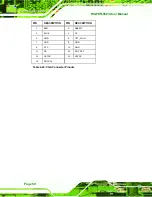
PIN NO.
DESCRIPTION
PIN NO.
DESCRIPTION
25
TFT_R0
26
TFT_R1
26
TFT_R2
28
TFT_R3
29
TFT_R4
30
TFT_R5
31
TFT_R6
32
TFT_R7
33
GND
34
GND
35
FPCLK
36
T_VSYNC
37
TFT_EN
38
T_HSYNC
39
N/C
40
L_VDDEN
Table 4-17: TFT LCD TTL Port Connector Pinouts
4.3.15 USB Connector (Internal)
CN Label:
CN11
CN Type:
9-pin header (2x4)
CN Location:
See
7
Figure 4-17
CN Pinouts:
See
7
Table 4-18
The 9-pin USB connector provides connectivity to two USB 1.1 or two USB 2.0 ports. The
USB connector can support two USB devices. The USB ports are used for I/O bus
expansion.
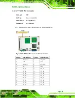
Figure 4-17: USB Connector Pinout Locations
Summary of Contents for WAFER-8523
Page 16: ...WAFER 8523 User Manual Page 1 Chapter 1 1 Introduction...
Page 22: ...WAFER 8523 User Manual Page 7 Chapter 2 2 Detailed Specifications...
Page 36: ...WAFER 8523 User Manual Page 21 Chapter 3 3 Unpacking...
Page 40: ...WAFER 8523 User Manual Page 25 Chapter 4 4 Connectors...
Page 66: ...WAFER 8523 User Manual Page 51 Chapter 5 5 Installation...
Page 91: ...WAFER 8523 User Manual Page 76 Chapter 6 6 BIOS Screens...
Page 127: ...WAFER 8523 User Manual Page 112 Chapter 7 7 Software Drivers...
Page 154: ...WAFER 8523 User Manual Page 139 Appendix A A BIOS Options...
Page 158: ...WAFER 8523 User Manual Page 143 Appendix B B Terminology...
Page 162: ...WAFER 8523 User Manual Page 147 Appendix C C Watchdog Timer...
Page 165: ...WAFER 8523 User Manual Page 150 Appendix D D Compatibility...
Page 168: ...WAFER 8523 User Manual Page 153 Appendix E E Hazardous Materials Disclosure...


