


WAFER-8523 User Manual
Page 42
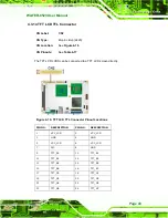
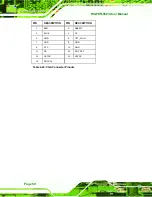
4.3.13 Serial Port Connector (COM2)
CN Label:
CN12
CN Type:
14-pin header (2x7)
CN Location:
See
Figure 4-15
CN Pinouts:
See
Table 4-16
The 14-pin serial port connector connects to the COM2 serial communications channels.
COM2 is a multifunction channel. In default mode COM2 is an RS-232 serial
communication channel but, with the COM2 function select jumper, can be configured as
either an RS-422 or RS-485 serial communications channel.
Figure 4-15: COM2 Connector Pinout Locations
PIN NO. DESCRIPTION
PIN NO.
DESCRIPTION
1
DATA CARRIER DETECT (DCD) 2
DATA SET READY (DSR)
3
RECEIVE DATA (RXD)
4
REQUEST TO SEND (RTS)
5
TRANSMIT DATA (TXD)
6
CLEAR TO SEND (CTS)
7
DATA TERMINAL READY (DTR) 8
RING INDICATOR (RI)
9 GND
10
N/C
11
12 TXD485#
13
14 RXD485#
Table 4-16: COM2 Connector Pinouts
Summary of Contents for WAFER-8523
Page 16: ...WAFER 8523 User Manual Page 1 Chapter 1 1 Introduction...
Page 22: ...WAFER 8523 User Manual Page 7 Chapter 2 2 Detailed Specifications...
Page 36: ...WAFER 8523 User Manual Page 21 Chapter 3 3 Unpacking...
Page 40: ...WAFER 8523 User Manual Page 25 Chapter 4 4 Connectors...
Page 66: ...WAFER 8523 User Manual Page 51 Chapter 5 5 Installation...
Page 91: ...WAFER 8523 User Manual Page 76 Chapter 6 6 BIOS Screens...
Page 127: ...WAFER 8523 User Manual Page 112 Chapter 7 7 Software Drivers...
Page 154: ...WAFER 8523 User Manual Page 139 Appendix A A BIOS Options...
Page 158: ...WAFER 8523 User Manual Page 143 Appendix B B Terminology...
Page 162: ...WAFER 8523 User Manual Page 147 Appendix C C Watchdog Timer...
Page 165: ...WAFER 8523 User Manual Page 150 Appendix D D Compatibility...
Page 168: ...WAFER 8523 User Manual Page 153 Appendix E E Hazardous Materials Disclosure...


