FDX-S Series User Guide
53
10.3.5 Background color
Menu
Top
→
OUTPUT IMAGE
→
BACKGROUND COLOR
Setting for
ALL, OUT01 to OUTn
Setting value R/G/B: 0 to 255 [Default] R/G/B: 0 (Black)
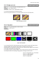
You can set the background color of output video signal.
Select “A” to change the settings of “R”, “G” and “B” relatively from the current setting values.
[Background: Gray]
[Background: Black (Default)]
[Fig. 10.2] Background color
10.3.6 Test pattern
Menu
Top
→
OUTPUT IMAGE
→
TEST PATTERN
Setting for
OUT01 to OUTn
Setting value
256STEP GRAY
OFF [Default]
COLOR BAR
16 STEP GRAY
RED RASTER
GREEN RASTER BLUE RASTER
WHITE RASTER
VERTICAL
STRIPE
CROSS HATCH
OUTPUT FRAME
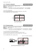
[Fig. 10.3] Test pattern
You can activate the FDX-S
’s internal test pattern generator and direct its signal to each output connector.
“OUTPUT FRAME”: Select this pattern if part of image is not displayed on the sink device.
Setting parameters for Image position and
Image size
on the output side will be adjusted in order to present
the test pattern appropriately on the display device.
For test patterns other than “OUTPUT FRAME”: Video is output on full screen with the resolution format as
set in Output resolution and the settings of Image position, and Image size
will be invalid.
【
See: 10.3 Output position, size, and masking
【
【
【
Scan conversion output only
Scan conversion output only


