background image

FDX-S Series User Guide 

44 

9.3.5  Automatic reload 

To set automatic reload interval of [CROSSPOINT], [VIEW STATUS], and [HDBT STATUS] windows: 

1.  Select [SYSTEM SETTINGS] from [MENU]. 

2.  Select the desired interval in 5-seconds increments (5 to 60 seconds) for [AUTO RELOAD TIME]. 


If you select [OFF] for [AUTO RELOAD TIME] (default), [CROSSPOINT] and [VIEW STATUS] windows 

are not updated automatically. 


[Fig. 9.8] Setting automatic reload interval 


9.3.6  Saving/Restoring settings 

To save settings to a PC as a backup file: 

1.  Select [SYSTEM SETTINGS] from [MENU]. 

2.  Click the [BACKUP] button of [BACKUP/RESTORE]. 


[Fig. 9.9] Saving settings 


Summary of Contents for FDX-S Series

Page 1: ...User Guide Ver 1 0 0 Thank you for choosing our product To ensure the best performance of this product please read this user guide fully and carefully before using it and keep this manual together wi...

Page 2: ...e United States and other countries Microsoft Windows Internet Explorer are either registered trademarks or trademarks of the Microsoft Corporation in the United States and other countries The terms M...

Page 3: ...l device pursuant to part 15 of the FCC Rules These limits are designed to provide reasonable protection against harmful interference when the equipment is operated in a commercial environment This eq...

Page 4: ...he warning is ignored or the product is handled incorrectly Indicates the presence of a hazard that may cause minor personal injury or property damage if the caution is ignored or the product is handl...

Page 5: ...may cause the connection to overheat increasing the risk of electrical shock or fire Do not use a damaged plug or connect to a damaged outlet Unplug the product from the AC power source during install...

Page 6: ...the product is damaged by falling or having been dropped If you continue to use the product under these conditions it may increase the risk of electrical shock or fire For maintenance and repair conta...

Page 7: ...or higher above sea level Failure to do so may shorten the life of the internal parts and result in malfunctions When mounting the product into the rack provide sufficient cooling space Mount the pro...

Page 8: ...2 4 Coaxial cable 28 8 3 Connecting control devices 29 8 3 1 RS 232C communication 30 8 3 2 LAN communication 30 8 3 3 Alarm 31 8 4 Connecting power cord 31 9 Operation 32 9 1 Powering on off 32 9 2 F...

Page 9: ...0 4 9 Sink device EDID check 60 10 4 10 Hot plug ignoring duration 60 10 4 11 Presence of output signal for when no signal is input No scan conversion 61 10 5 Input position size and cropping 61 10 5...

Page 10: ...Subnet mask 80 10 13 3 MAC address 81 10 13 4 TCP port number 81 10 13 5 HDBaseT Output LAN 81 10 13 6 HDBaseT Input LAN 81 10 14 Preset memory 82 10 14 1 Recalling crosspoint 82 10 14 2 Saving cross...

Page 11: ...information 98 10 18 Factory default list 99 11 Product specification 102 11 1 FDX S16U 102 11 2 FDX S16 103 11 3 FDX S32U 104 11 4 FDX S32 105 11 5 FDX SIV4H 106 11 6 FDX SIV4T 106 11 7 FDX SIV4S 107...

Page 12: ...16 S32 Max resolution 4K 60 4 4 4 4K 30 HDCP 1 4 2 2 1 4 Input 16 32 16 32 Output 16 32 16 32 Redundant power supply Optional FDX SRP16 SRP32 SRP16 SRP32 SRP16 SRP32 I O boards 4 I Os per board Input...

Page 13: ...ackets For FDX S32U S32 M4 screw Cable clamp One 1 power cord 6 ft 1 8 m Table 2 1 Included items Item FDX S16U S32U S16 S32 Frame 1 1 1 1 3 pin captive screw connector 1 1 1 1 2 pin captive screw con...

Page 14: ...e video signals up to 1080p 24 bit can be transmitted to 492 ft 150 m at maximum if using with IDK s HDBaseT products supporting 328 ft 100 m transmission 2 Up to 98 ft 30 m 1080p 60 Up to 39 ft 12m 4...

Page 15: ...40 m FDX SOV4HS Up to 984 ft 300 m over coaxial cable FDX SIV4S Motion adaptive interlaced progressive conversion FDX SOV4HS FDX SOV4TS Aspect ratio control Seamless switching with one black frame An...

Page 16: ...tatus Preset memory Last memory Connection Reset Button security lockout System check WEB browser control Redundant power supply Optional LAN and RS 232C transmission FDX SIV4T FDX SIV4UT 1 FDX SOV4T...

Page 17: ...FDX S Series User Guide 17 5 Panels 5 1 Frame 5 1 1 FDX S16U S16 Front panel Rear panels With redundant power supply Fig 5 1 Drawings...

Page 18: ...nector for 3G SDI HD SDI SD SDI signals SDI loop through output connector If the FDX is powered on the input SDI signals can be output from the SDI loop through output connectors HDMI output connector...

Page 19: ...FDX S Series User Guide 19 5 1 2 FDX S32U S32 With redundant power supply Rear panels Front panel Fig 5 2 Drawings...

Page 20: ...HDMI cable fixing holes Retain HDMI cables by inserting cable clamps HDBaseT input connector Input connector for HDBaseT signals Connects to a transmitter over a category cable SDI input connector In...

Page 21: ...scription Drawings Max resolution FDX SIV4H Input 4K 30 HDMI DVI 4K 1 4K 30 FDX SOV4H Output FDX SIV4T Input 4K 30 HDBaseT 4K 1 4K 30 FDX SOV4T Output FDX SIV4UH Input 4K 60 HDMI DVI 4K 2 4K 60 4 4 4...

Page 22: ...FDX S Series User Guide 22 5 3 Redundant power supply unit Redundant power supply units For Model Drawing FDX S16U S16 FDX SRP16 FDX S32U S32 FDX SRP32...

Page 23: ...T Up to 328 ft 100 m For monitoring Video switching T Controller HDBaseT Up to 328 ft 100 m SDI camera HDBaseT Up to 328 ft 100 m SD SDI Up to 1312 ft 400 m HD SDI Up to 787 ft 240 m 3G SDI Up to 459...

Page 24: ...provide adequate ventilation maintain sufficient clearances around the FDX S 1 2 in 30 mm or more Consider installing the FDX S in an environment compatible with the maximum temperature indicated in...

Page 25: ...to 328 ft 100 m R Transmitter Receiver T ICP Multi window Processor T Transmitter HDMI DVI Up to 98 ft 30 m HDMI DVI Up to 98 ft 30 m HDMI DVI HDMI DVI HDMI DVI HDMI DVI HDBaseT Up to 328 ft 100 m T T...

Page 26: ...ut and output connectors Both HDBaseT input and output connector support long reach mode With long reach mode video signals up to 1080p 24 bit can be transmitted to 492 ft 150 m at maximum if using wi...

Page 27: ...ry cables we recommend keeping a distance between the cables or not to place the cables closely in parallel Keep the category cable running as straight as possible Looping or coiling the cable causes...

Page 28: ...Check the Table 8 1 above If the problem persists it may be necessary to shorten the category cable 8 2 4 Coaxial cable Select the appropriate coaxial cable by referring to the following table Table 8...

Page 29: ...FDX S Series User Guide 29 8 3 Connecting control devices LAN Video switching Controller Fig 8 3 Application example for control devices Example FDX S16U...

Page 30: ...4 Connecting RS 232C cable to 3 pin captive screw connector 8 3 2 LAN communication The FDX S includes the function that is equivalent to those of switching hub It enables connections between the FDX...

Page 31: ...cooling fans internal temperature and board 28 AWG to 16 AWG conductor gauge is recommended The recommended wire strip length is 0 28 in 7 mm Up to 0 28 7 mm Fig 8 5 Connecting cable to 2 pin captive...

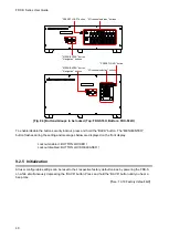
Page 32: ...e alarm power on both of POWER 1 and POWER 2 switches To shut down the FDX S turn off both switches within five seconds With redundant power supply Fig 9 1 POWER 1 and POWER 2 After powering on the FD...

Page 33: ...Displays menu on the front display Arrow buttons and Navigates menu BACK button Returns to the previous hierarchy Top Main menu Setting menu Sub menu MENU ENTER button BACK button FDX S16U 16X16 Matri...

Page 34: ...energy saving mode and the front display goes back to the top page See 10 16 7 Channel selection mode See 10 16 4 Displaying advanced menu See 10 16 5 Power saving SELECT MODE INPUT OUTPUT Select an i...

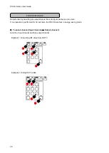
Page 35: ...annel Example 1 Outputting IN1 video to OUT3 The selected output channel button flashes Example 2 Displaying IN5 video to all output channels The output channel that does not have board cannot be sele...

Page 36: ...hannel or vice versa If no operation is performed for 30 seconds the FDX S becomes in energy saving mode To select channel Input channel Output channel Select an input channel and then output channel...

Page 37: ...elect channel Output channel Input channel Select an output channel and then input channel Example 1 Outputting IN9 video to OUT13 Example 2 Displaying IN5 video to all output channels Example 3 Hidin...

Page 38: ...t memory that can be loaded from I O channel P N Preset memory FDX S16U FDX S16 No 01 to No 16 FDX S32U FDX S32 No 01 to No 32 See 10 14 Preset memory Example Loading preset memory No 07 to which IN1...

Page 39: ...nel selection buttons 0 to 9 Selecting No 1 Selecting No 15 Fig 9 3 Recalling preset memory 9 2 4 Front panel security lockout The front panel security lockout limits operation of the FDX S from the f...

Page 40: ...n security lockout press and hold the BACK button The MENU ENTER button flashes during the setting and messages below are displayed on the front display Lockout enabled BUTTON LOCKED Lockout disabled...

Page 41: ...9 3 1 Starting WEB browser To start WEB browser of the FDX S Step 1 Start the WEB browser Maximizing the window size would be recommended Step 2 Enter the IP address that is programmed into the FDX S...

Page 42: ...is set to OFF by default See 10 1 Menu Fig 9 6 Enabling advanced menu 9 3 3 Editing crosspoint name To edit crosspoint name 1 Click the NAME EDIT button from CROSSPOINT to open the NAME EDIT window 2...

Page 43: ...s if registration fails See 10 15 Bitmap Fig 9 7 Registering bitmap Table 9 3 Error message Message Description File Name is invalid The specified file name is not correct File Format Error is happene...

Page 44: ...al in 5 seconds increments 5 to 60 seconds for AUTO RELOAD TIME If you select OFF for AUTO RELOAD TIME default CROSSPOINT and VIEW STATUS windows are not updated automatically Fig 9 8 Setting automati...

Page 45: ...t dialog appears during the operation Note Do not power off the FDX S or perform WEB menu operation until restoring finishes Fig 9 10 Restoring settings 9 3 7 Initialization To initialize settings 1 S...
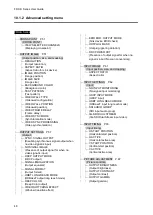
Page 46: ...ting menus You can switch setting menu advanced menu using the MENU ENTER button FUNCTION SELECT SYSTEM SETTINGS ADVANCED MENU The number of I O channels varies depending on the model n in this sectio...

Page 47: ...ID CH FOR EXTERNAL MODE External EDID FRAME RATE Frame rate RS 232C SETTINGS P 80 RS 232C PARAMETERS RS 232C communication LAN SETTINGS P 80 LAN IP ADDRESS IP address SUBNET MASK Subnet mask MAC ADDRE...

Page 48: ...NAL EQUALIZATION Output equalizer SIGNAL FORMAT Output format HDBT LONG REACH MODE HDBaseT output long reach mode DEEP COLOR Deep Color output VIDEO SWITCHING EFFECT Window transition effect EDID ERR...

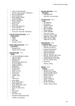
Page 49: ...ital Dolby Digital audio Dolby Digital Plus Dolby Digital Plus audio Dolby TrueHD Dolby TrueHD audio DTS DTS audio DTS HD DTS HD audio SPEAKER CONFIGURATION Speaker configuration RS 232C SETTINGS P 80...

Page 50: ...enu POWER SAVE MODE Power saving TOP PAGE Top page SELECT MODE Channel selection mode VIEW STATUS P 95 Status indication SINK DEVICE STATUS Sink device status SINK DEVICE EDID Viewing sink device EDID...

Page 51: ...x960 1080i 59 94Hz WSXGA 1680x1050 WXGA 1280x800 1080i 50Hz UXGA 1600x1200 WXGA 1280x768 720p 59 94Hz WXGA 1600x900 XGA 1024x768 720p 50Hz WXGA 1440x900 VGA 640x480 576p 50z SXGA 1400x1050 480p 59 94H...

Page 52: ...0 to 2100 0 by 0 1 Default 0 0 Vertical position 2100 0 to 2100 0 by 0 1 Default 0 0 The image position is based on the output resolution 100 and it starts from the upper left quadrant Image size sho...

Page 53: ...L STRIPE CROSS HATCH OUTPUT FRAME Fig 10 3 Test pattern You can activate the FDX S s internal test pattern generator and direct its signal to each output connector OUTPUT FRAME Select this pattern if...

Page 54: ...position Menu Top OUTPUT IMAGE VIDEO WALL POSITION Setting for OUT01 to OUTn Setting value H Not control 01 to 20 Horizontal display position First to 20th from left Default 01 V Not control 01 to 20...

Page 55: ...unction can be enabled only in synchronization mode 10 3 10 Synchronization mode Menu Top OUTPUT IMAGE VIDEO SYNC MODE Setting for SLOT01 to SLOTn Setting value THROUGH Ignores and lets synchronous si...

Page 56: ...ch video output signal If not signals cannot be synchronized Table 10 2 Synchronization Example 2x2 and 4x2 Setting Setting for 2x2 4x2 Synchronization mode SLOT03 MASTER B MASTER A SLOT04 SLAVE SLAVE...

Page 57: ...o the selected input To enable this function set 10 4 1 Disabling synchronous signal output when no video signal is input to OFF See 10 3 5 Background color See 10 15 Bitmap 10 4 3 HDCP output Menu To...

Page 58: ...etting value AUTO Default HDMI 422 DVI HDMI RGB HDMI 444 HDMI 420 Available only for 4K 59 94 50 You can select an output signal mode and color space of the output video The selected mode has priority...

Page 59: ...it 36Bit You can select the color depth of HDMI signal 30bit and 36Bit If signals are input with 30Bit or 36Bit and a sink device supporting Deep Color is connected the signals are output at 30Bit or...

Page 60: ...audio output and the like may occur ERROR2 and ALWAYS2 are only for FDX SIV4UT FDX SIV4UH boards Notes This setting is applied when HDMI signal is input and 10 4 5 Output format is set to a format oth...

Page 61: ...0 5 1 Aspect ratio Menu Top INPUT IMAGE ASPECT RATIO Setting for IN01 to INn for each input signal Setting value Table 10 6 Restoring aspect ratio For input signal Setting value TV signal PC signal AU...

Page 62: ...an output from that source device Changing EDID ON OFF Requesting source device to output video signal Monitoring Hot plug ON OFF Video signal from source device Fig 10 7 Monitoring absence of input N...

Page 63: ...cumstances and if the content is indeed not protected the problem can be solved by setting this menu to DISABLE Video with copyright protection Video without copyright protection HDCP compliant PC Vid...

Page 64: ...4 Default 2 1 Audio group 1ch to 4ch 2 Audio group 5ch to 8ch 3 Audio group 9ch to 12ch 4 Audio group 13ch to 16ch Up to 16 audio channels are in SDI input audio and these channels are divided into o...

Page 65: ...cal lines Vertical start position Video to be displayed to sink device Fig 10 10 Input area 10 7 1 Horizontal start position Menu Top INPUT TIMING H START POSITION Setting for IN01 to INn for each inp...

Page 66: ...efault 0LINE You can set the vertical start positions of input video If the set value exceeds the limitation mentioned below the display start position will be set automatically to a value within the...

Page 67: ...lue 0 to 200 Default 100 You can set the brightness level for each output signal 10 8 2 Output contrast Menu Top PICTURE ADJUSTMENT OUTPUT CONTRAST Setting for ALL OUT01 to OUTn Setting value R G B 0...

Page 68: ...g value 5 to 15 Default 0 NORMAL You can set the desired level of sharpness for each input signal 10 8 6 Input brightness Menu Top PICTURE ADJUSTMENT INPUT BRIGHTNESS Setting for IN01 to INn for each...

Page 69: ...set the color saturation independently for each input signal 10 8 10 Input video correction initialization Menu Top PICTURE ADJUSTMENT INPUT SETTING INIT Setting for IN01 to INn for each input signal...

Page 70: ...for ALL OUT01 to OUTn Setting value 0ms to 256ms Default 0ms You can adjust the time gap between video motion and audio sound 10 10 Input audio 10 10 1 Stable input audio wait Menu Top INPUT AUDIO SE...

Page 71: ...ternal EDID Copy DATA Changing speaker configuration Fig 10 12 Setting EDID 10 11 1 External EDID Menu Top EDID SETTINGS CH FOR EXTERNAL MODE Setting for ALL IN01 to INn Setting value OUT1 to OUTn You...

Page 72: ...setting while an HDR supported sink device is connected or if copied EDID of an HDR supported sink device is selected for EDID setting 3D is supported if external EDID is selected for EDID setting wh...

Page 73: ...ee 10 11 1 External EDID Setting value Maximum resolution Pixels Standard Remarks 11 WXGA 1280 768 VESA 12 WXGA 1280 800 MAC supported 13 Quad VGA 1280 960 14 SXGA 1280 1024 15 WXGA 1360 768 16 WXGA 1...

Page 74: ...N N N N N N N N N N N 15 1360 768 Y Y Y Y Y Y Y Y Y Y N N N N N N N N N N N N N N 16 1366 768 Y Y Y Y Y Y Y Y Y Y N N N N N N N N N N N N N N 17 1400 1050 Y Y Y Y N Y Y Y Y Y Y N N N N N N N N N N N...

Page 75: ...ault EDID will be applied 10 11 4 HDMI DVI Menu Top EDID SETTINGS SIGNAL FORMAT Setting for ALL IN01 to INn Setting value HDMI Default DVI You can select EDID signal format This setting will be valid...

Page 76: ...f a poor quality or an excessively long cable is connected In such a case the noise may be removed by setting the color to 24Bit Press the MENU ENTER button to apply the setting Note For 4K 50 59 94 6...

Page 77: ...1kHz 32kHz You can set the maximum Dolby Digital audio sampling frequency that is output from the source device This setting will be valid only if one of 05 to 45 is selected for EDID in 10 11 2 Reso...

Page 78: ...F Default 96kHz 48kHz 44 1kHz 32kHz You can set the maximum DTS audio sampling frequency that is output from the source device This setting will be valid only if one of 05 to 45 is selected for EDID i...

Page 79: ...aker configuration Number of speakers FL FR LFE FC RL RR RC FLC FRC RLC RRC FLW FRW FLH FRH TC FCH 2 Default ON OFF OFF OFF OFF OFF OFF OFF OFF OFF OFF 2 1 ON ON OFF OFF OFF OFF OFF OFF OFF OFF OFF 5...

Page 80: ...eck NONE EVEN ODD NONE Stop bit bit 1 2 1 You can set the RS 232C communication Press the MENU ENTER button to apply the setting 10 13 LAN 10 13 1 IP address Menu Top LAN SETTINGS IP ADDRESS Setting v...

Page 81: ...ication command control at maximum 8 CONNECTION Connections will be assigned to 8 communication command controls at maximum For communication command control set the port number to a value from 1100 6...

Page 82: ...emory Press the MENU ENTER button to apply the setting See 10 14 2 Saving crosspoint 10 14 2 Saving crosspoint Menu Top USER PRESET STORE CROSSPOINT Setting for 01 to 32 STORE CROSSPOINT 01 STORE CROS...

Page 83: ...Setting value Default Output channel OUT OUT0 to OUTn OUT Video input channel not control 1 to n OFF Memory name NAME 20 to 7D of ASCII code 20 space You can edit crosspoint memory settings Select th...

Page 84: ...mory Menu Top USER PRESET STORE PRESET SETTINGS Setting value No 1 to No 32 You can save up to 32 preset memories and name these memories up to 10 characters from ASCII 20 to 7D You can skip the namin...

Page 85: ...14 Start up setting Setting value Description LAST CHANNEL Default Starts with the settings last time the FDX S powered off CHANNEL OFF Turns channel OFF PRESET MEMORY 1 to PRESET MEMORY 32 Starts wi...

Page 86: ...monochrome 1 bit 16 colors 4 bits 256 colors 8 bits 16 77 million colors TRUE COLOR 24 bits Resolution The maximum resolution Horizontal resolution Vertical resolution The number of bytes per pixel 8...

Page 87: ...olor of the bitmap Select A to change the settings of R G and B relatively from the current setting values 10 15 3 Aspect ratio Menu Top BITMAP ASPECT RATIO Setting for ALL OUT1 to OUTn Setting value...

Page 88: ...T TOP LEFT You can set the image position of the bitmap CENTER Default TOP LEFT BOTTOM LEFT TOP RIGHT BOTTOM RIGHT Fig 10 21 Position 10 15 5 Start up bitmap output Menu Top BITMAP START UP BITMAP Set...

Page 89: ...ton OUTPUT SELECT button I O channel selection buttons LOCK Default UNLOCK MENU MENU ENTER button Navigation buttons LOCK Default UNLOCK PRESET PRESET LOAD button LOCK Default UNLOCK You can set front...

Page 90: ...acters flash See 8 3 3 Alarm SYSTEM STATUS MAIN FAN TEMP IN OUT Fig 10 23 Alarm page Table 10 17 Alarm description Note In case an alarm is output the FDX S may have problems Please contact us Values...

Page 91: ...ormal setting menu or Advanced setting menu 10 16 5 Power saving Menu Top SYSTEM SETTINGS POWER SAVE MODE Setting value ON Default OFF If you select ON and no button function is operated for 10 or 60...

Page 92: ...0 Input signal status 2 Gr 2 INPUT STATUS 2 01 h08t 444 YUV 709L Input signal status 3 Gr 3 INPUT AUDIO STATUS 01 L PCM 192kHz M Input signal status 4 Gr 4 SLOT01 01 02 03 04 H D H H A H A Gr 5 Sink d...

Page 93: ...frequency No Signal No signal is input When no input board is installed is displayed Audio channel M 2 1ch or higher multi audio No value Stereo Mono 4 Input board number Input status for each input...

Page 94: ...nt 12 36 bit pixel 12 bit component Stream type T HDCP 2 2 stream type 1 t HDCP 2 2 stream type 0 No value with HDCP HDCP 1 4 Color space RGB RGB supported 422 YCbCr 4 2 2 supported 444 YCbCr 4 4 4 su...

Page 95: ...to video output connectors See 10 16 6 Top page 10 17 2 Viewing sink device EDID Menu Top VIEW STATUS SINK DEVICE EDID You can display the EDID information of the sink device that is connected to eac...

Page 96: ...d board status See 10 16 3 Alarm Note In case an alarm is output the FDX S may have problems Please contact us Displayed value Description MAIN Appears in case an abnormality in the power supply volta...

Page 97: ...iption Value to be displayed FDX SIV4H Input 4K 30HDMI DVI 2D FDX SOV4H Output FDX SIV4T Input 4K 30 HDBaseT 2T FDX SOV4T Output FDX SIV4UH Input 4K 60 HDMI DVI 4D FDX SOV4UH Output FDX SIV4UT Input 4...

Page 98: ...played the FDX S may have problems Please contact us 10 17 7 Power supply voltage status Menu Top VIEW STATUS POWER STATUS You can view the power supply voltage status OK means normal and NG means abn...

Page 99: ...BIT COLOR VIDEO SWITCHING EFFECT ON EDID ERR OUTPUT MODE OFF HOTPLUG MASK OFF DDC POWER OUT ON INPUT IMAGE ASPECT RATIO AUTO INPUT SETTINGS NO INPUT MONITORING 10 sec HDCP INPUT MODE FDX SIV4UH FDX SI...

Page 100: ...MAT HDMI FRAME RATE 60 Hz DEEP COLOR 24 BIT Linear PCM 48 kHz AAC OFF Dolby Digital OFF Dolby Digital Plus OFF Dolby TrueHD OFF DTS OFF DTS HD OFF SPEAKER CONFIGURATION 2 ch FL FR RS 232C SETTINGS PAR...

Page 101: ...IMAGE POSITION CENTER START UP BITMAP OFF SYSTEM SETTINGS BUTTON LOCK TARGET MENU PRESET CHANNEL LOCK BEEP SOUND ON ALARM ON ADVANCED MENU OFF POWER SAVE MODE ON SELECT MODE INPUT OUTPUT TOP PAGE OFF...

Page 102: ...240 VAC 10 50 Hz 60 Hz 3 Hz Power consumption About 20 Watts Dimensions 16 9 5 2 15 7 430 W 132 H 400 D mm 3U high Excluding connectors and the like Weight 26 9 lbs 12 2 kg With redundant power supply...

Page 103: ...er control Status notification HDBaseT status display General Power 100 240 VAC 10 50 Hz 60 Hz 3 Hz Power consumption About 20 Watts Dimensions 16 9 5 2 15 7 430 W 132 H 400 D mm 3U high Excluding con...

Page 104: ...Hz 60 Hz 3 Hz Power consumption About 42 Watts Dimensions 16 9 8 7 15 7 430 W 221 H 400 D mm 5U high Excluding connectors and the like Weight 32 8 lbs 14 9 kg With redundant power supply 35 9 lbs 16...

Page 105: ...er control Status notification HDBaseT status display General Power 100 240 VAC 10 50 Hz 60 Hz 3 Hz Power consumption About 40 Watts Dimensions 16 9 8 7 15 7 430 W 221 H 400 D mm 5U high Excluding con...

Page 106: ...ntioned above 11 6 FDX SIV4T Item Description Input 4 inputs Video HDBaseT HDBaseT HDCP 1 4 36 bit Deep Color For WUXGA QWXGA and 4K 24 25 30 4 4 4 Deep Color is not supported x v Color 3D ARC HEC CEC...

Page 107: ...EDID emulation Format VGA to 4K Dot clock 25 MHz to 600 MHz For WQHD WQXGA only Reduced Blanking is supported 480i 480p 576i 576p 720p 1080i 1080p 4K For 4K format 24 Hz 25 Hz 30 Hz 50Hz 4 4 4 60 Hz 4...

Page 108: ...n distance Up to 492 ft 150 m 1080p 24 bit in Long reach mode For Long reach mode use IDK s HDBaseT Products that supports 328 ft 100 m or longer 11 10 FDX SOV4H Item Description Output 4 outputs Vide...

Page 109: ...he FDX S s output and sink device this feature may be invalid 11 12 FDX SOV4HS Item Description Output 4 outputs Video HDMI DVI HDMI DVI 1 0 TMDS single link HDCP 1 4 TMDS clock 27 MHz to 202 5 MHz TM...

Page 110: ...tal cables However the Connection Reset feature will fix these problems automatically without the need to physically plug and unplug the cables It creates the same condition as if the cable were physi...

Page 111: ...sed The distance may not be extended with some device combinations cabling method or other manufacturer s cable Video may be disturbed or may not be output even if signals are within the range mention...

Page 112: ...the EDID resolution setting of this device set to the input resolution supported by the sink device Vertical sync frequency For TV output resolutions 480i to 4K video of 59 94 Hz or 60Hz may not be ou...

Page 113: ...ise If a long cable is connected for input or output when 4K 30 60 HDMI DVI digital I O board is installed replace it with a 16 ft 5 m or shorter cable Since the FDX S has automatic cable length equal...

Page 114: ...p and bottom sides are cut off Some sink devices overscan input video and the video may be cut out Check the display setting of the sink device Video is reduced vertically or horizontally Some sink de...

Page 115: ...Even though multi channel audio is played only 2 channel audio is output For multi channel change the EDID setting which is set to 2 channel audio by default If the problem still cannot be solved chec...

Page 116: ...perform the following tests and then contact us No Checking items Result 1 The problem occurs at all connectors Yes or No 2 Connect the devices using genuine cables without connecting the FDX S The pr...

Page 117: ...JAPAN TEL 81 46 200 0764 FAX 81 46 200 0765 Email idk_eng idk co jp URL http www idkav com USA IDK America Inc 72 Grays Bridge Road Suite 1 C Brookfield CT 06804 TEL 1 203 204 2445 Email sales idkav c...

Reviews: